My last few blog posts have been about bringing up example boards designed in our HDL, especially ones incorporating the new features of port arrays and multipack devices. Some of them were more toy examples and intended as proofs-of-concepts (like the LED matrix), while others were more practical - like the BLE multimeter and the source-measure unit. Over the past weeks, I've been racing solar cars, and putting those more practical boards to use.

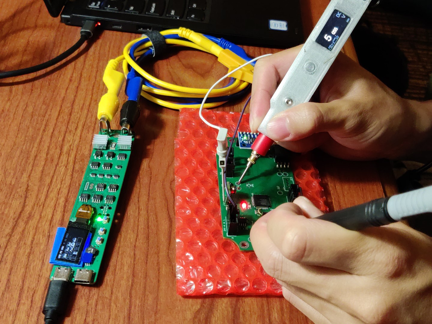
It's practically a tradition to bring up new hardware at the race. This is debugging the sensors board, but using test equipment designed in this HDL - the source measure unit on the left to power the test board while verifying output voltages with the BLE multimeter
I ended up bringing two designs with me, both designed as highly portable, field instruments. First was the USB source measure unit, a programmable DC power supply that is powered off of USB power delivery. Instead of massive chunky instruments possibly needing blocky transformer bricks, this slim device takes in USB PD (such as from any modern laptop charger) and generates up to the supply voltages - typically about 20V. The second is the BLE multimeter, a more recent design and which now has a case, which can be used to measure voltages. No more digging for the chunky multimeter that we always manage to misplace and never have on us when we need it, this one is small and portable that I can carry it with me and have it always ready.

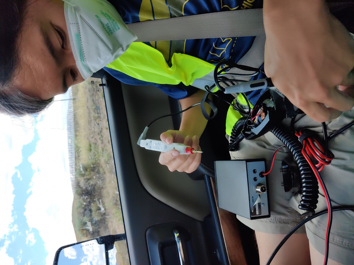
The portability is really nice, because you never know when you will need a multimeter. Like when your CB radios stop working on the road, and you want to debug them. To be fair, we never did figure out what was wrong, but having instruments ready meant that we could verify basic voltages and continuity - mainly, that the switches were indeed working
And not only are these practically useful devices, but they also showcase recent design system features, like port-array-enabled generators and newly refactored power converters.
So, what's next? Well, all those designs need revision. While the BLE multimeter was designed for 300V as a circuit, I didn't account for clearance in the layout, so it's probably not great about 80V or so. The next version could also be shrunk - perhaps using 0402 components, or (even automatically - hint hint) exploring component trade-offs that could reduce board area. The source measure unit in particular is an older design that could use a refresh. On the practical side, it needs a thermal design that isn't "slap some DRAM heatsinks on it and hope it didn't overheat" (spoiler, it did, though that was months ago in stress testing). Part of that could be a switching pre-regulator to reduce the heat dissipated by the linear power stage - and perhaps there's a best bang-for-the-buck design point that optimizes capability while minimizing cost and area. And it too should have some wireless connectivity, though for a more bench instrument maybe that's WiFi with an integrated webserver interface instead of BLE to a smartphone.

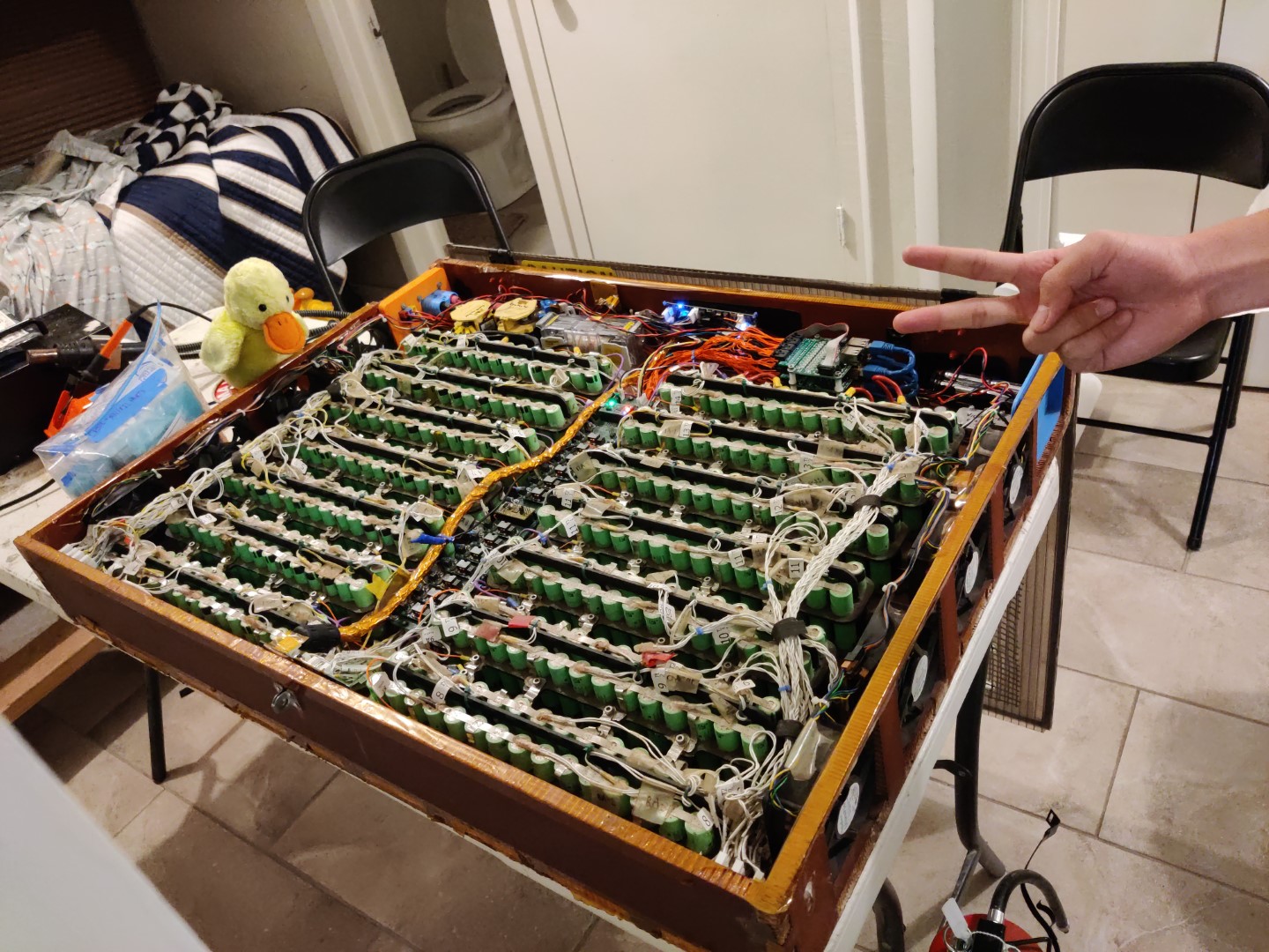
Pre-race: re-wire the battery box to eliminate screw connectors, because screw connectors are terrible under vibration (this has been a problem every. single. year.). The BLE multimeter was used to verify individual cell voltages and connectivity, though I didn't have the guts to measure the entire pack voltage and potentially blow everything up on day 0. I'll probably do some high voltage testing under more controlled settings in lab.