Introduction
What's the goal for this specific project?
Building lightweight corrugation structures that satisfy stiffness requirement while optimize the weight (as low as possible).
What have been accomplished so far and what will be accomplished?
(1) We have developed easy-to-use analytical models to predict the stiffness of double layer corrugation mechanism.
(2) We have validated the model, good accuracy.
(3) I am working on using the analytical models as a design constraint, along with geometry contrains and other constrains, to design origami robot based on minimum weight mertic.
Model Validation Result
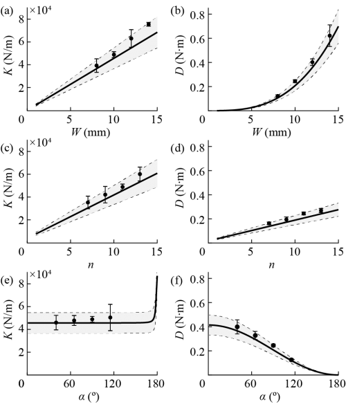
Caption: Modeling validation. (a-b) Varying plate width \(W\) while fixing number of creases \(n\) and crease fold angle \(\alpha\). (a) Compression stiffness. (b) Bending stiffness. (c-d) Varying number of creases \(n\) while fixing plate width \(W\) and crease fold angle \(\alpha\). (c) Compression stiffness. (d) Bending stiffness. (e-f) Varying crease fold angle \(\alpha\) while plate width \(W\) and fixing number of creases \(n\). (e) Compression stiffness. (f) Bending stiffness. Dots and error bars indicate mean testing results and standard deviations, solid lines indicate modeling results, dashed lines indicate 20% above and below modeling results and shaded regions indicate 20% error ranges. Sample size \(N=3\).
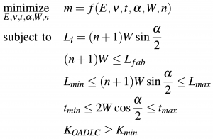
Optimization
Constraints:
1. Geometry Constraints:
Theoretically, the layout of the OADLC mechanism can be any shape. For demonstration purposes, we use a rectangular shape and a circular shape. For a rectangle, the totally length of each layer along chordwise direction when folded should be the same as the crease length of the other layer, so that the chordwise stiffness on one layer and the spanwise stiffness on the other both contribute to the total stiffness, reducing the rectangle into a square. These constraints can be expressed as follows:
\begin{equation} L_i = (n + 1) W \sin{\frac{\alpha}{2}}å \end{equation}
When designing the circular mechanism, length \(L_{j}\) will vary based on their locations. These constraints can be described as follows:
\begin{equation} L_{j} = 2 \sqrt{ (\frac{(n + 1) W \sin{\frac{\alpha}{2}}}{2})^2 - (| j - \frac{n + 1}{2} | W \sin{ \frac{\alpha}{2})^2 } } \end{equation}
Other layouts, e.g. triangle and trapezoid, can also be defined in the same manner.
2. Fabrication Constraints:
(1) Maximum fabrication dimension \(L_{fab}\): the maximum dimension of each layer when laying flat should be smaller then the maximum fabrication dimension \(L_{fab}\). Therefore, we have \(\max{(L_j)} \leq L_{fab}\) and \((n+1) W \leq L_{fab}\).
(2) Folded axial dimension [\(L_{min}\), \(L_{max}\)]: the dimension of the OADLC mechanism can be also limited within minimum dimension \(L_{min}\) and maximum dimension \(L_{max}\), depending on users need. Therefore, we have \(L_{min} \leq (n+1) W \sin{\frac{\alpha}{2}} \leq L_{max}\).
(3) Folded thickness [\(t_{min}\), \(t_{max}\)]: the thickness of the OADLC mechanism can be also limited within minimum thickness \(t_{min}\) and maximum thickness \(t_{max}\), depending on users need. Therefore, we have \(t_{min} \leq 2 W \cos{\frac{\alpha}{2}} \leq t_{max}\).
Note: we are not limiting crease number \(n\), plate width \(W\) or crease fold angle \(\alpha\)!!!!
3. Behavioral Constraints:
The stiffness of the OADLC mechanism need to meet the minimum stiffness requirement (\(K_{min}\) and/or \(D_{min}\)). Therefore we have \(K_{OADLC} \geq K_{min}\) and/or \(D_{OADLC} \geq D_{min}\).
Optimization Problem:
Here, we only use in-plane stiffness with a rectangular layout as an example to demonstrate how we formulate our design problem into a well-defined constrained optimization problem.
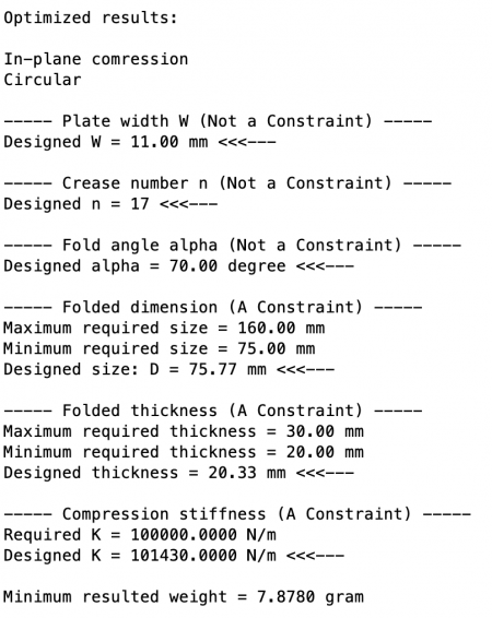
An Example: Wheels design for foldable cars
Geometry Constraints:
Circular shape + in-plane compression
Fabrication Constraints:
(1) Maximum fabrication dimension of the paper cutter: 250 mm
(2) We want the circular wheel to have a diameter between 75 mm and 160 mm, so that the foldable car has enough ground clearance and the wheels won't be too big (radius \(\leq\) car body length).
(3) We want the wheel to have a thickness between 20 mm and 30 mm, so that it is easy to mount the wheels and the wheels won't be too big.
Behavioral Constraints:
We want in-plane compression stiffness to be at least \(10^5\) N/m.
Design Result:
Case Study (Plan)
What will we demonstrate?
We will show, using our optimization approach, can can design corrugated structures that satisfy user specified requirements (constrains), while giving the lightest (cost-effective) design.
How will we demonstrate?
We need to show our approach works for different loading conditions (both compression and bending), and different shapes (both rectangule and circle).
Therefore, we will use two demos to show our approach can be used to design circles undering in-plane compression, and rectangules undering out-of-plane bending.
Demo Plan # 1: circles undering in-plane compression
I will design and build a foldable car with OADLC wheels. The above mentioned design parameters and results look great to me, I will use those for this demo.
What is in the demo: we will show a foldable car under compression (using the manuel material tester, showing load readings, compress the body of the entire car).
Demo Plan # 2: rectangules undering out-of-plane bending
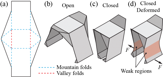
The gripper design seems to be a good example to use.
Here is a reminder of the gripper design: