Part 1: Correcting Y Direction Deflection
Y direction deflection correction
Following last week's blog post, I modified our design tool. The new results show a better match for y-direction deflection.
Here are some of the results:
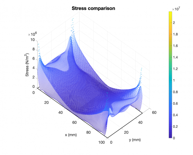
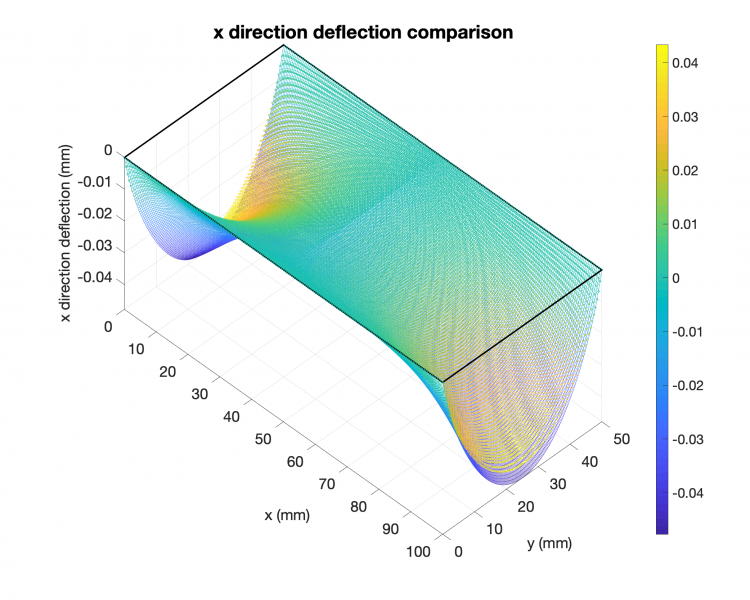
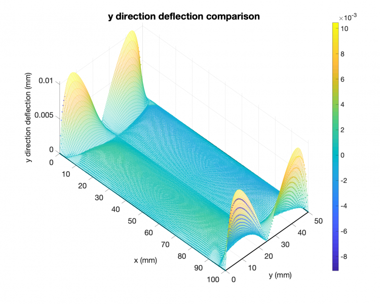
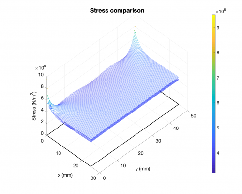
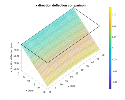
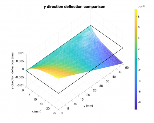
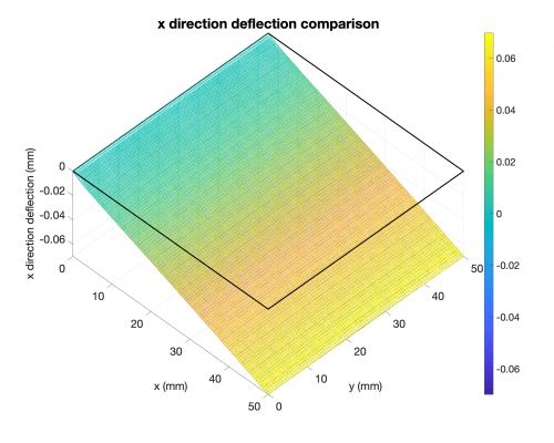
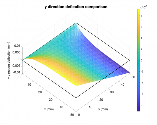
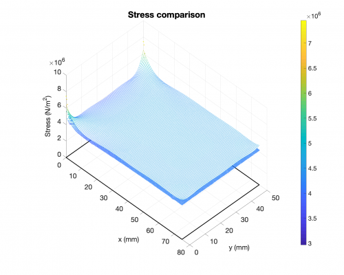
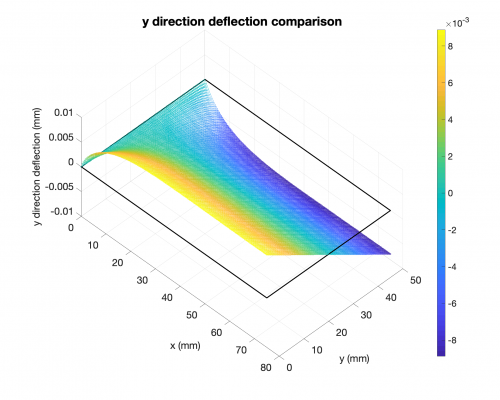
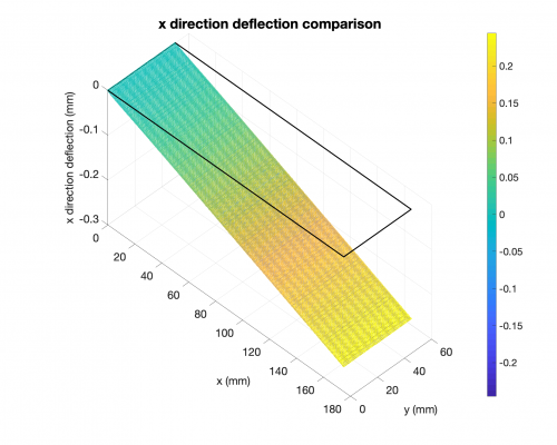
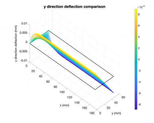
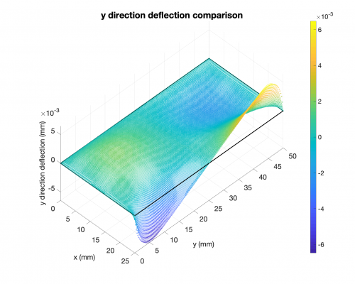
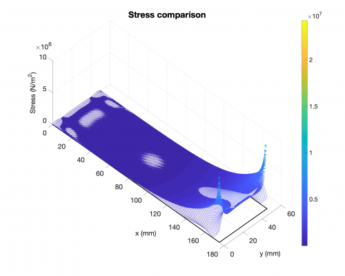
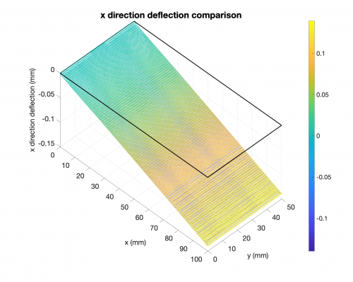
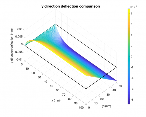
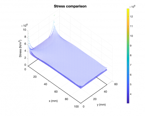
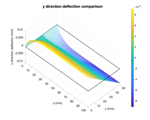
1. FCFC, clamped on longer edges, forces on shorter edges
(a) Stress distribution
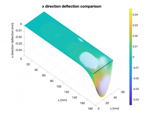
(b) x direction deflection
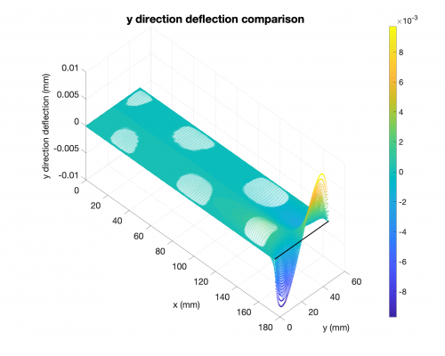
(c) y direction deflection
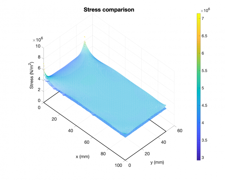
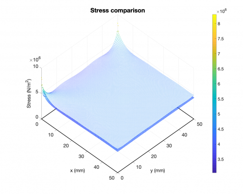
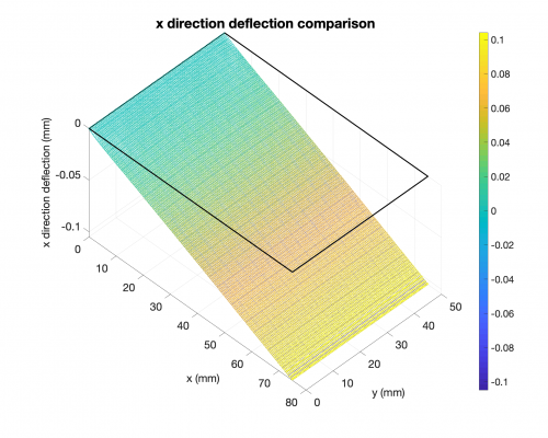
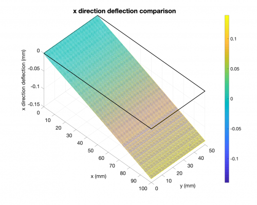
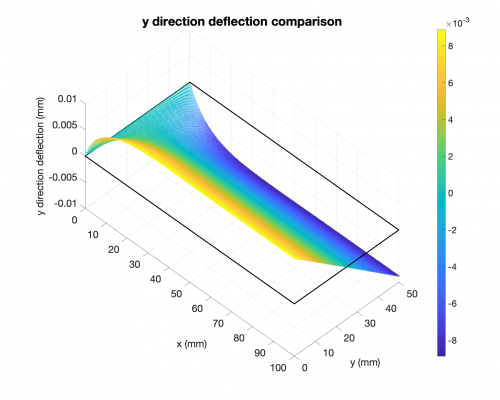
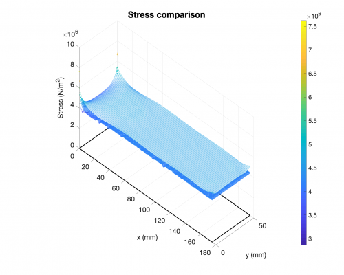
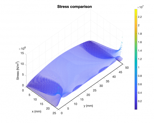
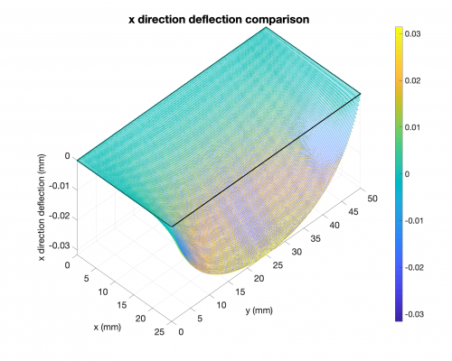
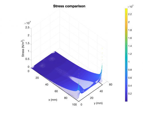
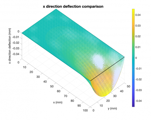
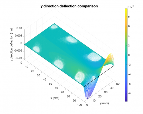
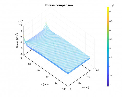
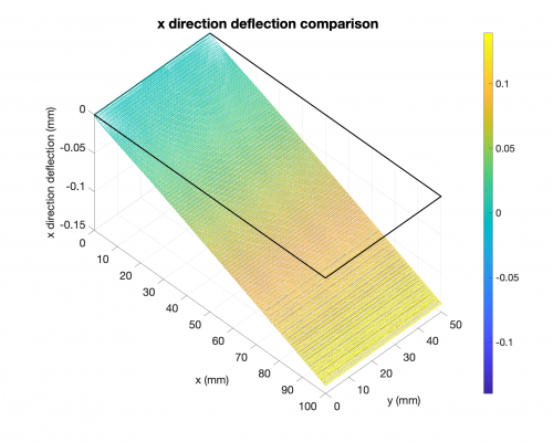
2. CFFF, clamped on one shorter edges, free on other edges, force on shorter edges
(a) Stress distribution
(b) x direction deflection

(c) y direction deflection

I noticed for some cases, e.g. clamped on shorter edges & free on longer edges & forces on longer edges, results do not match. Well if I swap the edges, results match well. I am trying to figure out what's wrong.
1. Study the effect of length, use CFFF case
(1) L = 25 mm
(2) L = 50 mm
(3) L = 75 mm
(4) L = 100 mm

(5) L = 175 mm
Conclusion: apparently, length is not the problem
2. Study the effect of boundary condition (& length), use CCFC case
(1) L = 25 mm
(2) L = 100 mm
(3) L = 175 mm
Conclusion: the problem seems to be the mixed BCs. It looks like the results (from our design tool and FEA) are on the same magnitude, which i am glad to say i think we can move on from this problem.
Part 2: Extending Boundary Conditions
Problem statement: I recently noticed, we need to extend the boundary conditions from 'constrained & not constrained' to the general 'simply-supported, clamped and free'. So here is an upgrade of our design tool.
The next thing to do is to deal with different boundary conditions: currently, BC constraints works only for clamped and free BCs. I am working on implementing simply-supported BC constraints.
- One thing to think about: at least one edge needs to be clamped, or rigid motion will occur.
- In plane stress analysis, out-of-plane deflection is not considered, so it's only in-plane deflections u and v. For u and v, free edges and simply-supported edges have the same effect -- free movement on the (u, v) coordinate surface.
- So here is the example case of CSSS (one shorter edge clamped):
(1) Face clamped: in FEA, plate has thickness, so here i first checked the behaviors when the whole face is clamped. Results show very good match.
(2) Edge clamped: here i checked the behaviors when the bottom edge is clamped. Results show very good match.
Intermedium conclusions: clamping edge and clamping face do not show significant difference. Results are close.