This week, the ORCAS team set finished setting up our learning environment and began running the first tests. To do this, we first needed to create a parameterized robot design that we could use in our simulations. Our initial plan was to use a two wheeled robot as the robot for which we would opt...
This week, me and Prathyush worked on implementing the algorithms we discussed in our blog posts from last week (here and here). So far we have our baseline algorithm from previous research implemented and are in the process of implementing our proposed algorithm. The two main components of the...
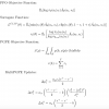
This past week me and Prathyush worked on formulating an algorithm to use to co-optimize structure and control. Due to the difference in how geometric and control parameters may affect the robot's reward, past research has separated the optimization of the two, choosing to iterate between optimizing...
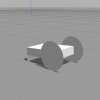
A Seg Bot in Gazebo This week, I worked on creating a Seg Bot model in Gazebo, the robot simulation engine that we are planning on using for our project. The Seg Bot model was created in the SDF format, an XML file format used by Gazebo to specify physical structures such as robots. The SDF format...

The UCLA LEMUR GitHub In anticipation of the release of RoCo, UCLA LEMUR now has a GitHub account!. You can check it out here.
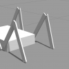
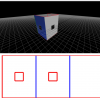
The SegBot in the interface This week, Prathyush and I worked on building the "SegBot" car in the mechanical interface. To do this, we had to fix/add multiple features, and there are still a few things left to do before the design is perfect. The two main obstacles if creating the car were adding...
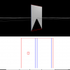
A component in the interface with cutouts added This week I spent trying to fix the issues that I have been working on the past couple of weeks. After spending a considerable time reading documentation and trying out different things in the code, I was able to make the cutouts appear in the 3D vie...
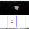
The interface without the cutout showing in the 3D view This week was spent trying to work out a lot of the bugs that were discovered last week during the addition of cutouts to the interface. When cutouts were first added, there was a problem with the generation of the 3D view of the component. T...
First attempts to add cutouts to the interface This week I continued my work with Wenzhong on adding finger joints as a option for creating output with Roco. We made some progress in figuring out how to create our own custom tabs as a method of adding the finger joints, however our current method...
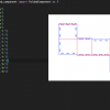
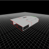
Automatically added tabs for a cube structure This week, I worked on improving how the RoCo system handles connections. RoCo is designed to allow users to easily fabricate 3D robot designs in a number of ways. Often, this involves breaking up or flattening the geometry, which causes the need for a...