Update:
- I found a typo in the modeling I presented last week. I has been revised.
- The new model makes sense by looking at the trends.
- The model is validated at some extreme situations (e.g. then crease folding angle alpha=180deg).
-
Out-of-plane bending is added to the analysis. So now we have both in-plane compression and out-of-plane bending.
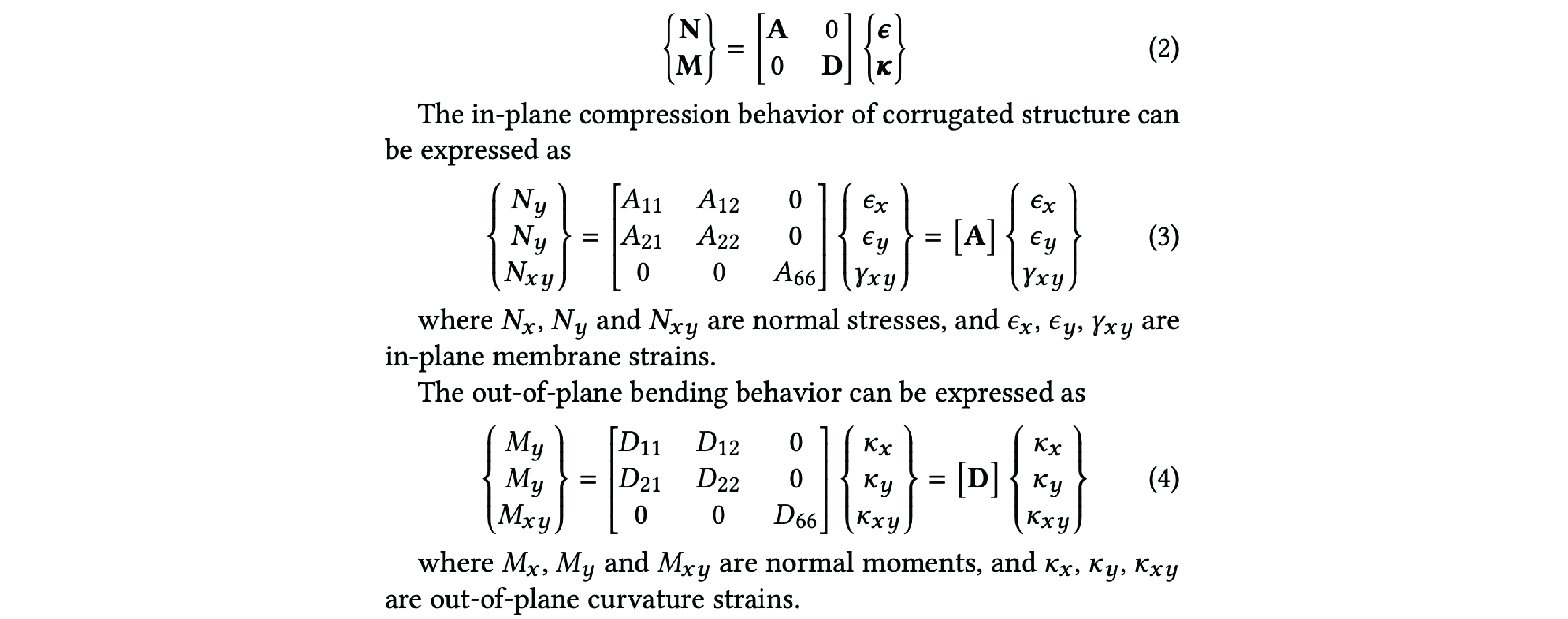
Details:
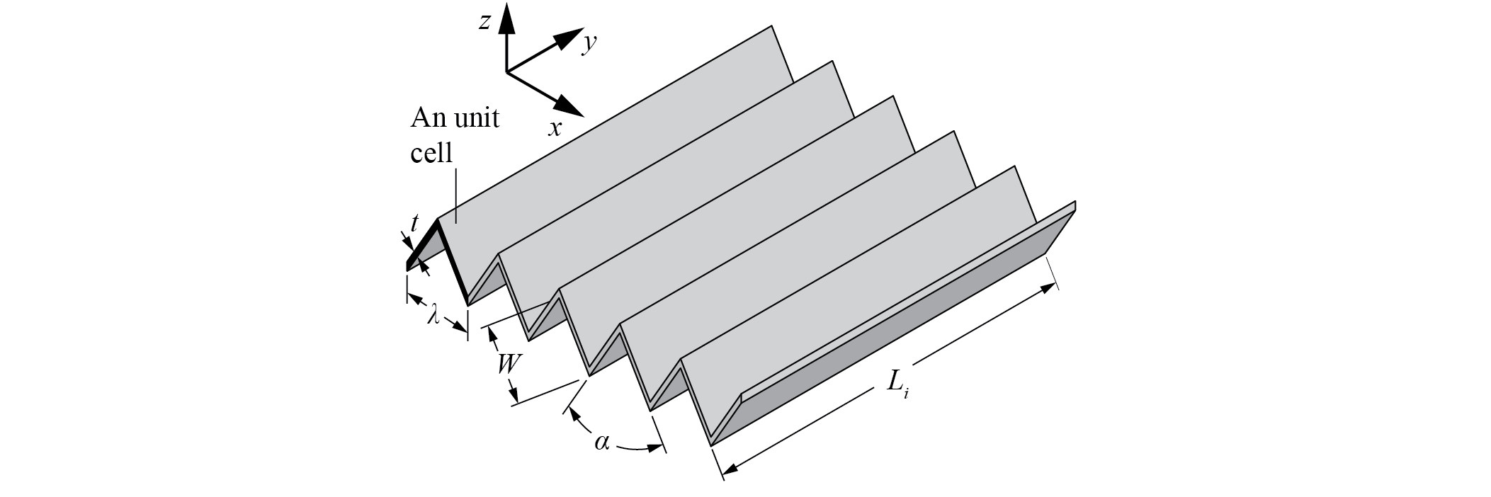
The modes are functions of the number of creases and crease folding angle.
- Number of creases is set from 1 to 1000, which is not practical, but we need it to see the trend.
- Crease folding angle is set from 0 degree to 180 degree. When crease folding angle is 180 degree, it is the extreme case I am interested in, which is when the currugated shape is flat and can be seen as a flat plate.
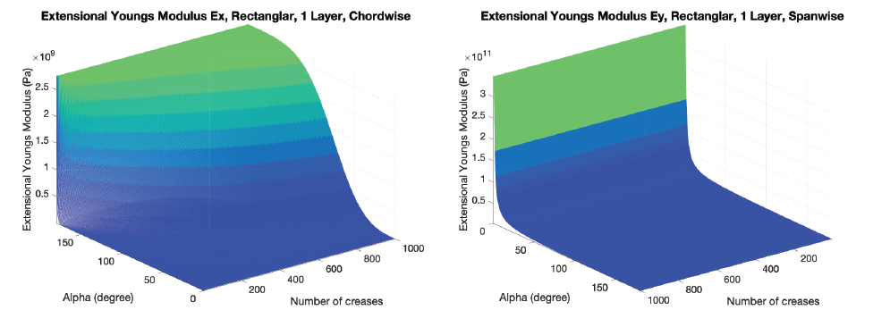
Model Trends:
Single Layer, In-Plane Compression Young's Modulus
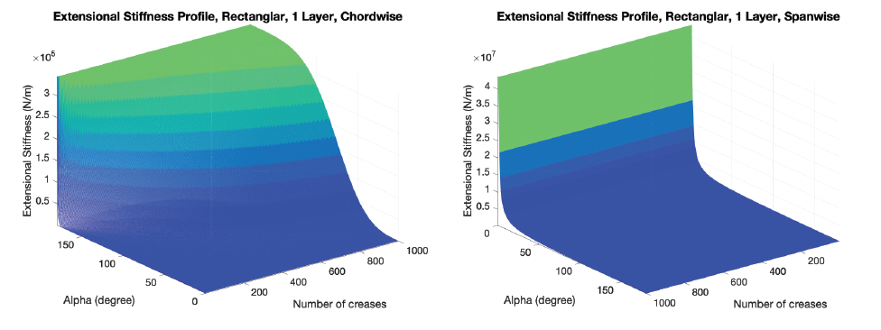
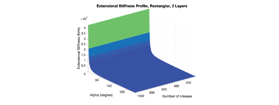
Single Layer, In-Plane Compression Stiffness
Double Layers, In-Plane Compression Stiffness
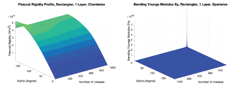
Single Layer, Out-of-Plane Bending Young's Modulus

Single Layer, Out-of-Plane Bending Flexural Rigidity
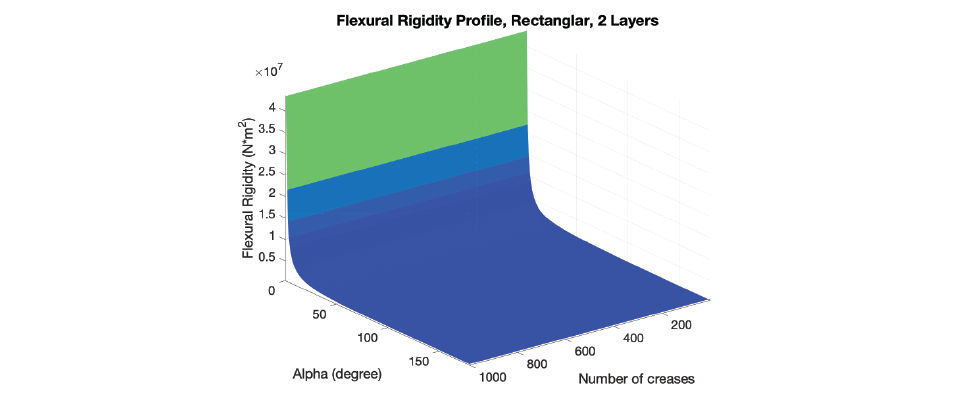
Double Layers, Out-of-Plane Bending Flexural Rigidity
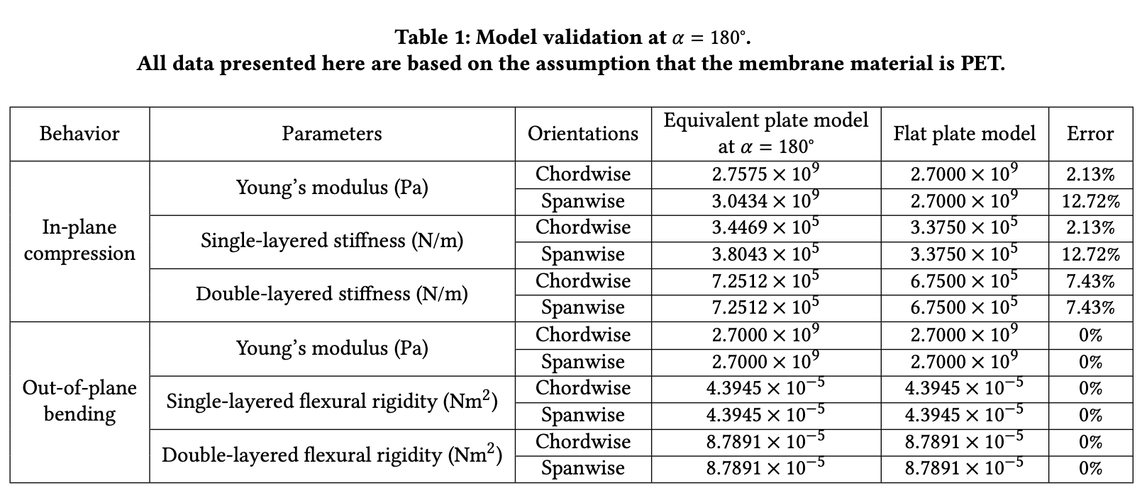
Model Validations:
At an extreme case when alpha = 180deg, no matter how many creases are there, the corrugated structures (either single-layered or double-layered) will become flat sheets. Here we compare the compression Young's modulus, single layer compression stiffness, double layers compression stiffness, bending Young's modulus, single layer bending flexural rigidity and double layer bending flexural rigidity of corrugated structures at alpha = 180deg with those of flat plates made out of the same membrane material and dimension.
Computational Design:
There are only two design constrains:
- The maximum crease number: I manually set it to 15. From the model and our life experience, as we increase the number of creases, the stiffness increases. However, in real life, we can not make infinity number of crease, due to fabrication reason. I found out 15 would be enough difficult to fabricate, so I set the upper limit to 15.
- Maximum fabrication dimension. The cutter machine has a maximum cutting dimension, which is 250mm.
The input will be the size of the structure (maximum dimension). That's it.
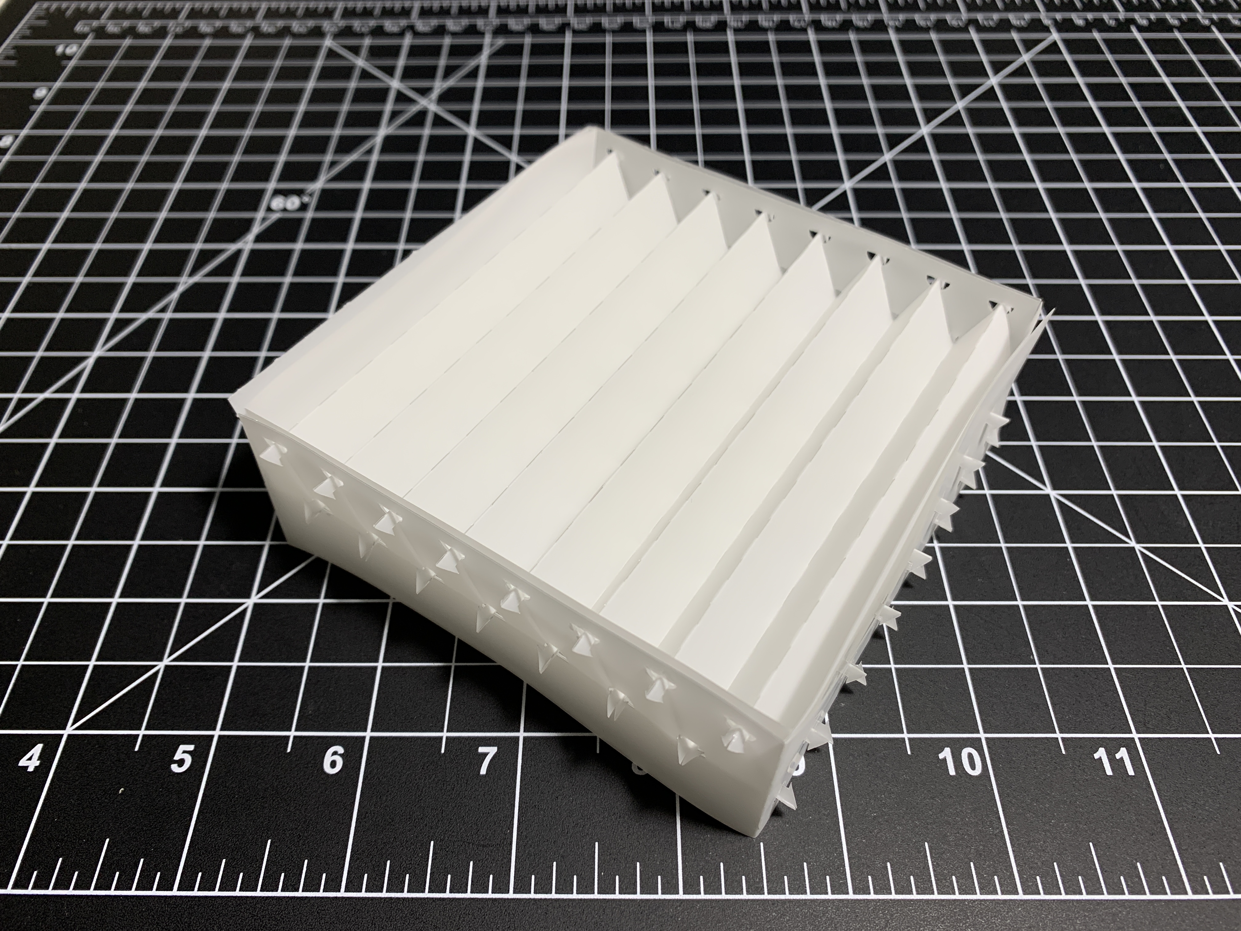
The program will automatically calculate and generate cut patterns according to maximum in-plane stiffness or out-of-plane stiffness requirements.
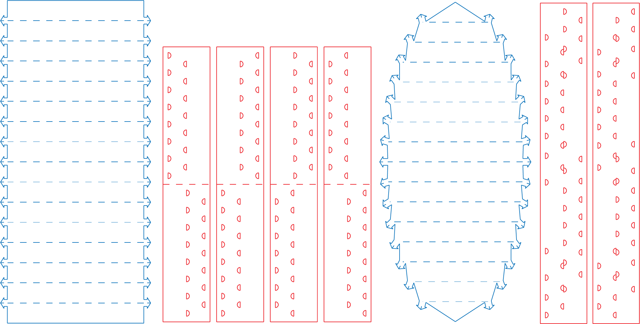
Here is an rectangular sample with 15 creases on each layer.
To-Do List:
- Physical sample validation using optimized design (Hard to finish, may skip this in this project. No machines to use to measure the Young's Modulus of the membrane material, and the stiffness of the corrugated structures. I have sent multiple emails to different groups, but due to safety reasons, there is no available help. It would be nice to buy a material tester for our future use, which I think will become quite handy.)
- Design implementation (Demo): I will make a car (4 wheels). The wheels will be made using the circular design, the body will be made using the rectangular design. One demo, two structures.
- Finishing up the paper.