Over the past week I have been reformulating the Kalman filter implementation by given it a more formal representation such that the system can be fully understand and built upon.
The image below shows the block diagram of the system from the highest level:
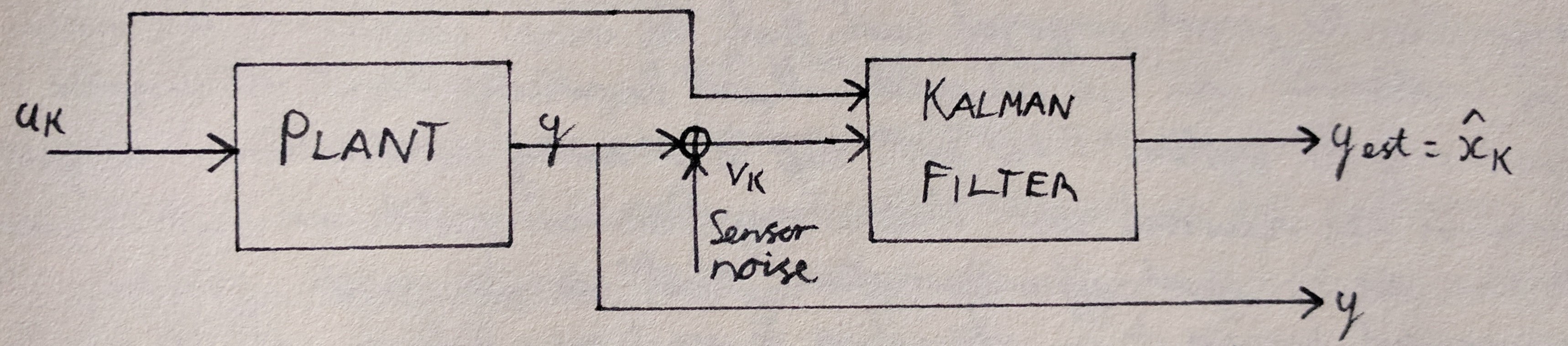
The plant model is assumed to be known but differs from an ideal system through the introduction of process noise which is modeled as a guassian random variable. The measurement reading is also assumed to be noisy and this is modeled with a gaussian distribution as well.
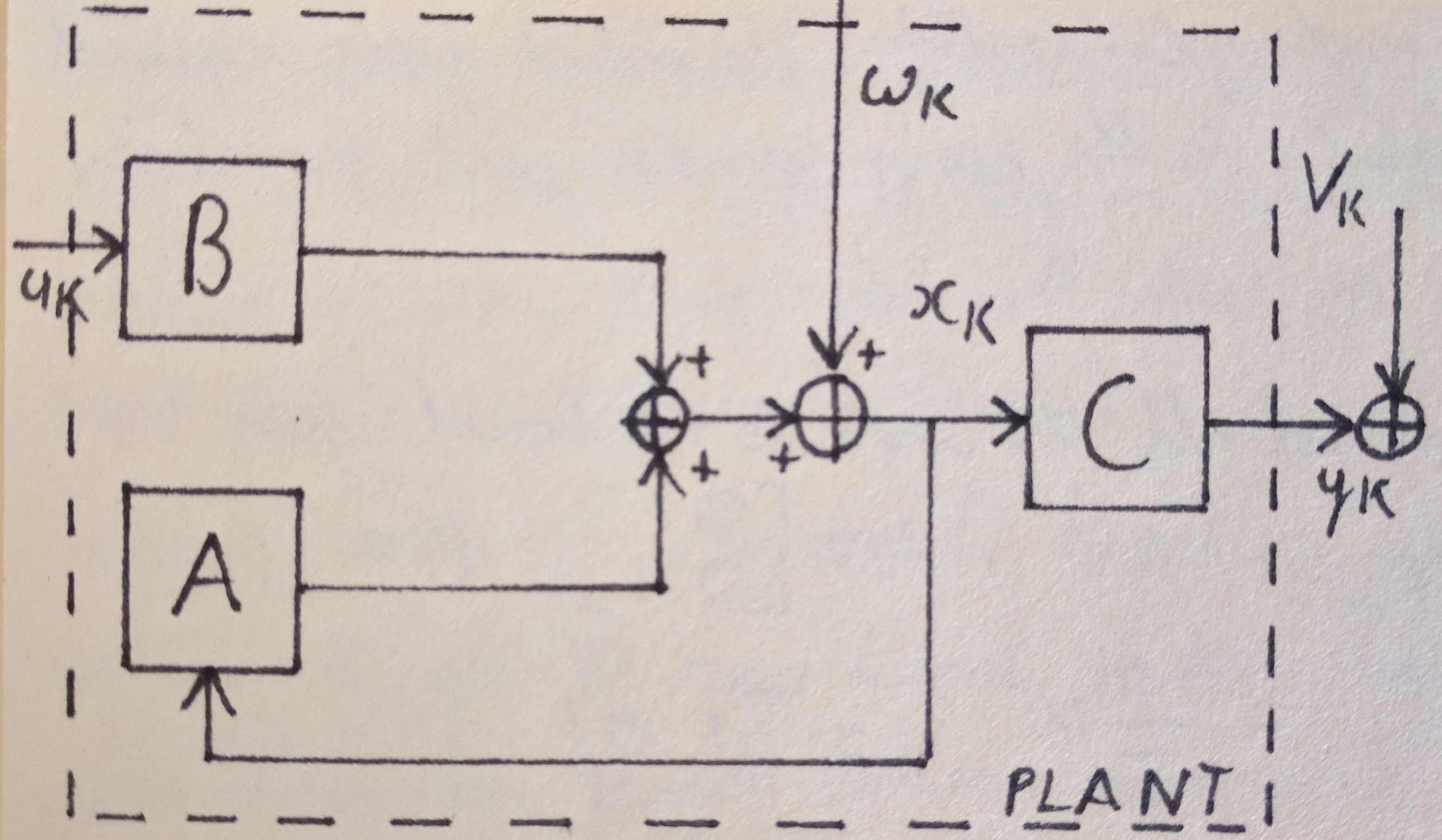
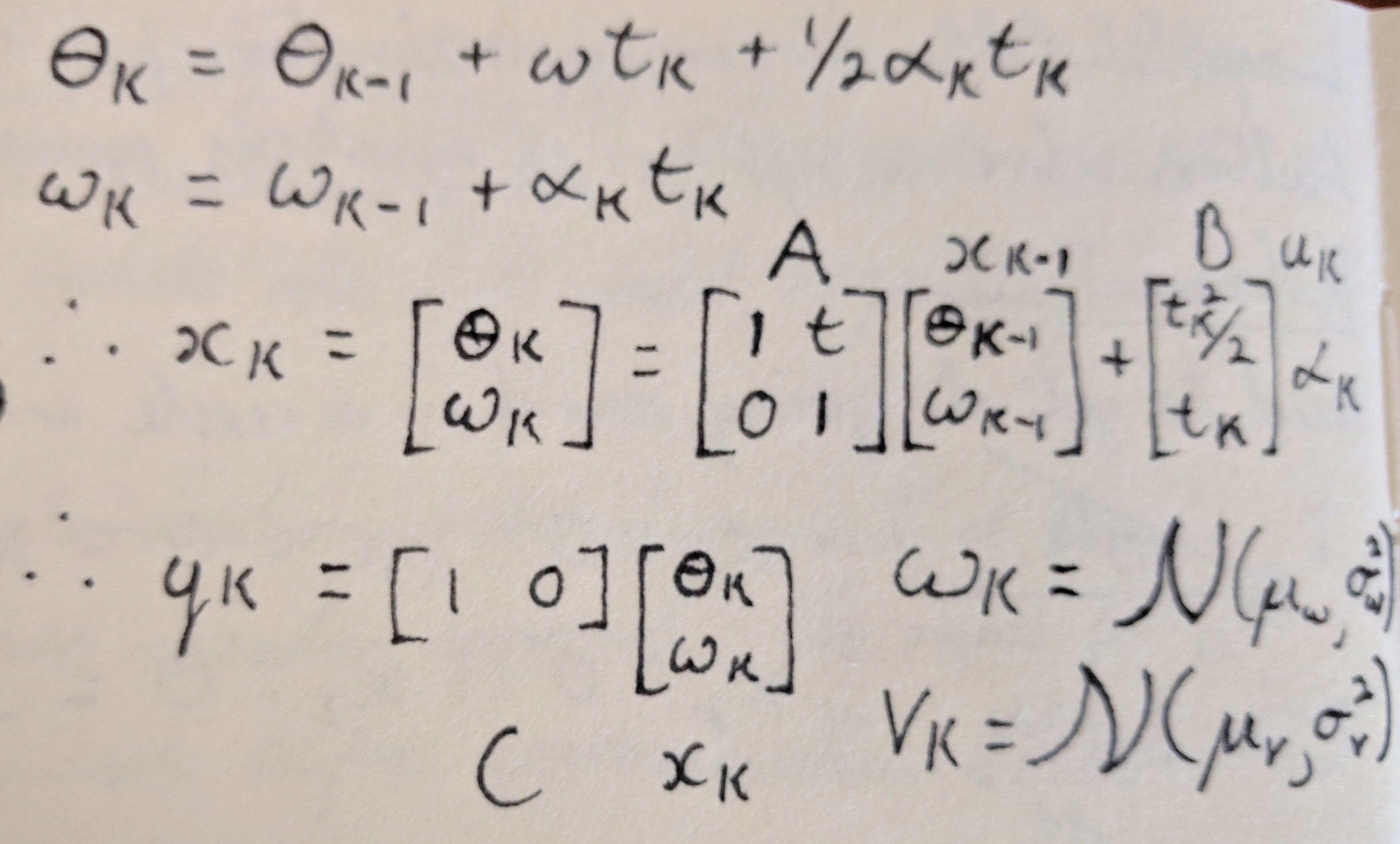
The image below shows the block diagram model of the system. To begin with we assume that the system is simply a body rotating in free space. The equations of motion are also shown below.
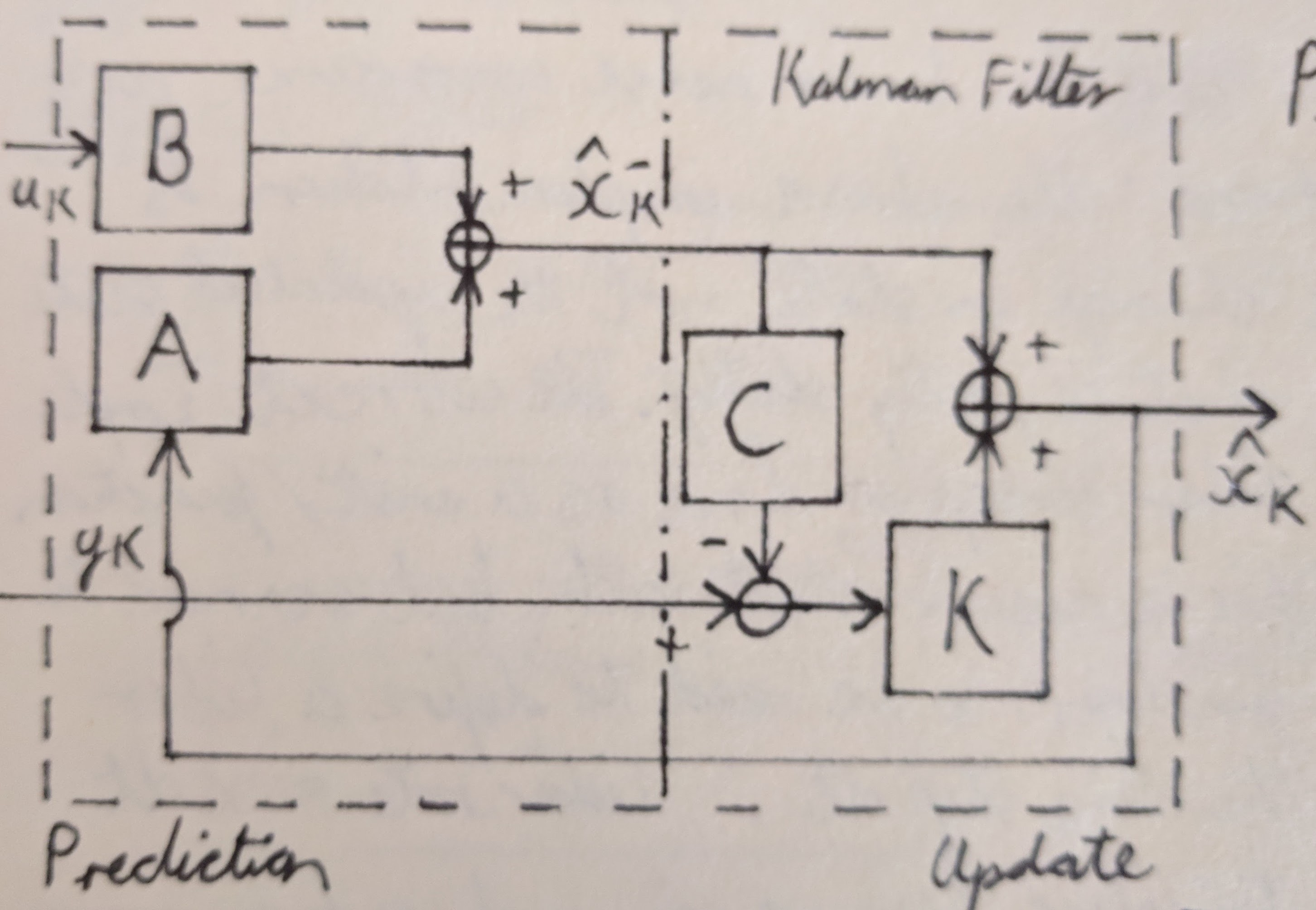
The image below shows the block diagram for the Kalman filter. The process is divided into two half according to the two stages of the Kalman filter, predication and update. For this implementation the state that we are trying to estimate is angular position. The Kalman filter process is shown in equation form below the block diagram. The computation for the kalman gain K is left out of the block diagram but is specified in the second image.
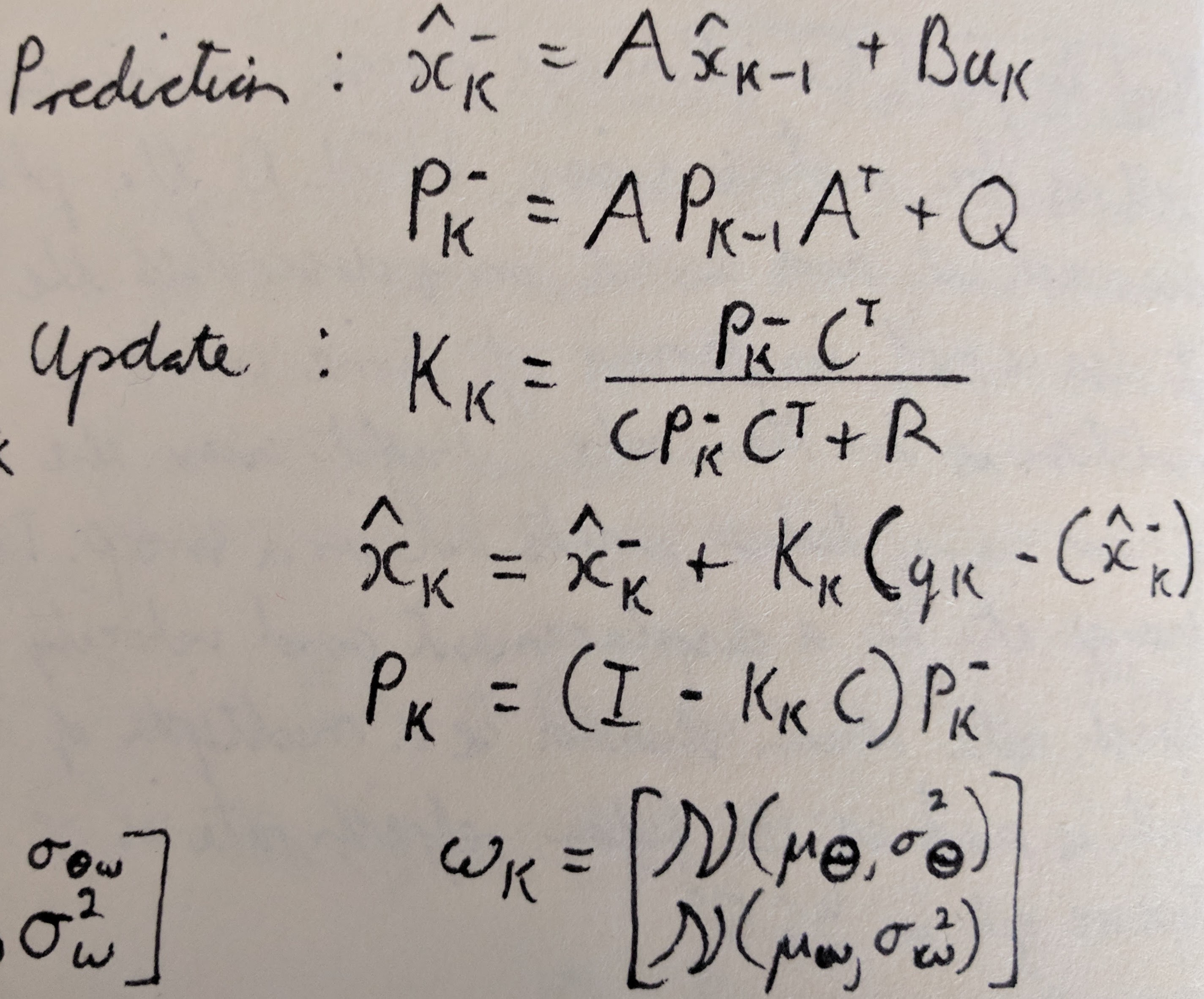
This implementation does not use the lidar reading to directly compute the room layout, which is the end goal, however it is a stepping stone to achieve that goal