Validation of our approach
How compare accuracy
There are different ways of comparing result accuracy:
-
Ratio of the maximum deflection calculated by the numerical solution to the corresponding values obtained analytically [1] [2]
-
Ratio of deflection of deflection at a particular point (e.g. central point) calculated by the numerical solution to the corresponding values obtained analytically [3]
-
Difference between the maximum deflection calculated by the numerical solution and the corresponding values obtained analytically [4]
Demo
Material selection:
Requirements:
-
Isotropic: model assumption & easy to implement in FEA
-
Uniform thickness: model assumption
Possible selection:
-
Paper sheet: anisotropic, hard to model (unless we measure E and make assumptions, which i do not think is a good idea), easy to fabricate, easy to break
-
0.125mm thick PET sheet (the white one we have been using) or 1.6mm thick Polypropylene Sheets (I do prefer Polypropylene Sheets): easy to fabricate, easy to break
-
Wood (assume plywood in lab): anisotropic, hard to model, easy to fabricate, break under larger force
-
Metal shim (spring steel): mm thick (can this one be cut using the laser (hopefully yes)? if not, it can also be hand cut), not gonna be easy to break (unless we provide a lot of force, which is hard to do on a small sample).
Furniture general dimension:
I would like to make sure we are using the correct size for the demos.
I would say, the flat plate surface dimension on any furniture will be about 120mm x 120mm, for the sake of:
-
Easy to fabricate: laser cutter will be used, and other components on the furniture may also be designed to connect with the loading plate
-
Easy to apply load: not too small that is hard to put objects (assuming metal blocks purchased from McMaster)
Furniture selection: shapes, boundarys and loading
The selection of Furniture need to satisfy the following requests:
-
Presenting different shapes (it will be nice to include at least one irregular shape)
-
Using different boundary conditions
-
Using different loading conditions: uniform loading, patch loading, point loading (we do not need to present all of them, but at least two)
Here is a simple diagram:
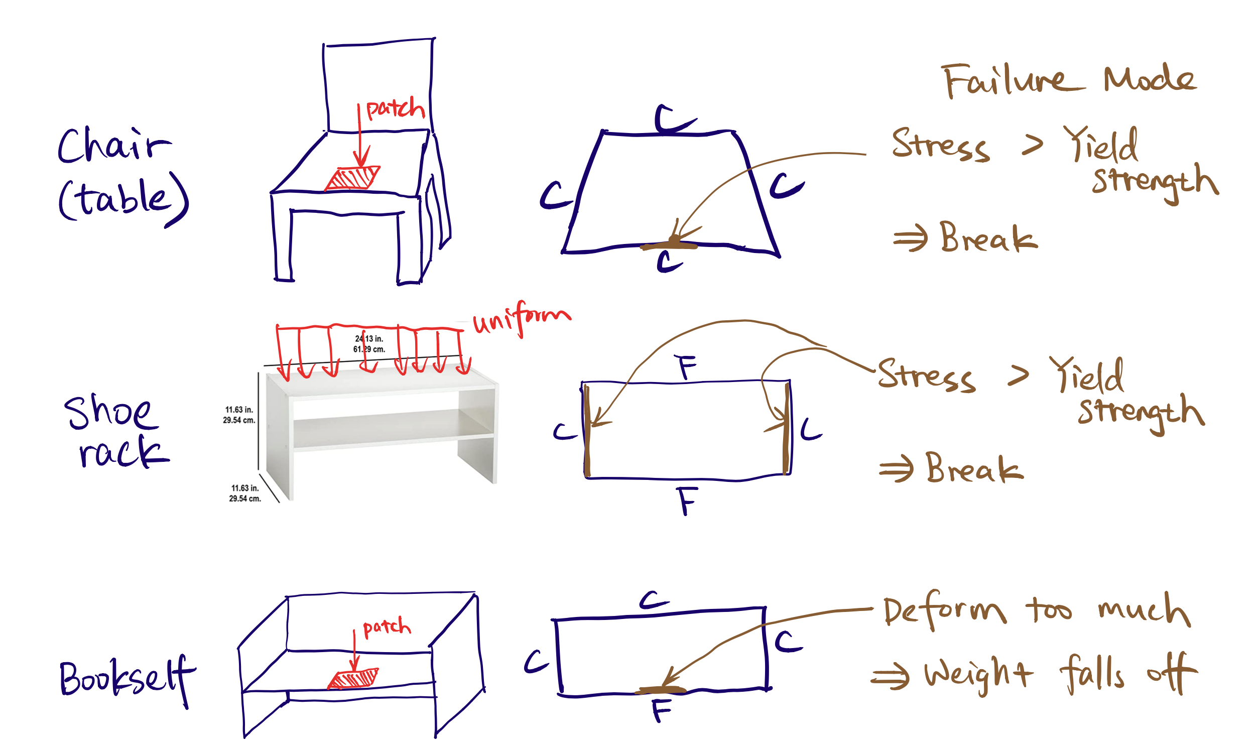
Failure demonstration
The failure needs to be relative easy to visualize. (Assume legs are a lot stiffer, so that we only worry about loading plate's bending problem.)
What to show:
-
Too much deformation
-
Too much stress (material yield / break)
Some ideas:
-
For a clamp-clamp-clamp-free rectangular plate, on the free edge and load is near edge, light weight --> deform slightly, but object stays; heavy weight --> large deformation causing weight to fall off the plate
-
For a clamp-free-clamp-free rectangular plate (a bookshelf or a shoe rack), uniform loading, light weight --> deform slightly, but object stays; heavy weight --> large deformation causing weight to fall off the bended plate
Practical throughts
Since we focus on the planar surface under transverse load, the other plate will be considered as infinite rigid.
In simulation and our design tool, this can be easily done by only analyze the bending plane.
However, in physical experiments, it is not easy to build foldable samples with infinite rigidity. So I plan to add (glue) one layer of 1.5mm thick acrylic on those side plates. What do you think?
Reference:
[1] Zozulya, V.V., 2011. Numerical solution of the Kirchhoff plate bending problem with BEM. International Scholarly Research Notices, 2011.
[2] Qin, Q.H., 1996. Transient plate bending analysis by hybrid Trefftz element approach. Communications in Numerical Methods in Engineering, 12(10), pp.609-616.
[3] Man, H., Song, C., Gao, W. and Tin‐Loi, F., 2012. A unified 3D‐based technique for plate bending analysis using scaled boundary finite element method. International Journal for Numerical Methods in Engineering, 91(5), pp.491-515.
[4] Saleeb, A.F. and Chang, T.Y., 1987. An efficient quadrilateral element for plate bending analysis. International Journal for Numerical Methods in Engineering, 24(6), pp.1123-1155.