IROS Submitted
I am happy to have our IROS paper submitted.
Here is our paper on arXiv.
Here you can find the demo video.
Here you can find all document (e.g. designs, codes, drawings). Here are all videos.
Thank you everyone for your support!
ICRA Accepted
Congratulations to Wenzhong, Ankur and me. Our ICRA paper is accepted.
Comments are gentle, so I guess revision will be minor. I have started and will finish it one week before spring break. I will send out the first revision draft by March 11 (next Thursday) for group comments and submit the final paper on March 18, 5pm. Then everyone can enjoy spring break a little bit.
Comments:
(1) "The contribution of the paper to robotics could have been explained better."
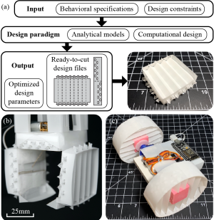
- Solutions: I have added demo figures into Fig. 1. I have also added one more paragraph in Intro section to discuss about the robotic side of contribution, which includes the robot car demo (moved it to the intro and concisely described it among other robotic applications). Last point in contributation section is expanded. "\textcolor{blue}{Beyond the foldable gripper, this computational design paradigm can be applied to boarder robotic community. To name a few: first, it can be applied to design various shapes of OADLC mechanisms with different mechanical specifications. For example, an origami-inspired foldable car derived from author's previous work \cite{mehta2014cogeneration} can be enhanced to gain more load-bearing capacity by replacing laminated wheels with computationally designed circular OADLC wheels (Fig.~\ref{fig: Intro_Figure}(c)). Second, it can be used to replace and customize building components for better performance. For example, in Liu \textit{et al.}, plastic corrugated sheets were used to build light weight self-folding robots \cite{liu2019self,liu2017self}. Though the corrugated sheets functioned well, they could be further customized to achieve desired rigidity while minimizing weight.}"
(2) "The paper would be clearer if the set of these design parameters were presented earlier."
- Solutions: I have added an explaination in intro section, to briefly explain what parameters we can change in our tool: "Thus, we develop analytical expressions of the in-plane stiffness and out-of-plane stiffness of this mechanism, \textcolor{blue}{which can be mathematically expressed as functions of design parameters, such as mechanical properties and geometry properties}"
(3) "The claim, in Section II, that the observed discrepancy is "mainly caused by the negligence of the connectors" seems speculative, and should be stated less definitively."
- Solution: I have changed the text into a less speculative way:"However, for simplicity reason, corrugated layers were modeled without considering the effect of connectors, which limited the movement of creases and also contributed to the combined stiffness. The effect could be observed in the experimental results as experimental data was slightly larger than the predictions from our model."
(4) "Several of the mathematical derivations could be presented in a more thorough manner."
- Question: I would like everyone's feedback on which equations we should explain more in details. Equations can be found here in our arXiv submission.
(5) "Yet still more detailed discussion for the numerical solution and its stability wrt how it translates to eventual design would be appreciated."
(6) "I would however have appreciated a discussion with respect to the quality of the designs achieved in general versus designs achieved by an experienced human given the same specifications."
Next
- Continue plate buckling research. Build a design tool for that problem. Submit a paper to:
-
2021 ASME International Mechanical Engineering Congress & Exposition(April 23)
-
2021 IEEE International Conference On Computer Aided Design (May 28)
-
2021 IEEE International Symposium on Experimental Robotics(TBD)
To-do list:
-
figure out a few demos that can showcase our design tool
-
do intuitive calculation first to proof the necessity of our design tool
-
finish tool implementation
-
build demonstration
-
write paper
- Help Wenzhong finish his logic gate journal paper.