Customizing Modular Components in RoCo to Allow for Easier Electronics Assembly
William Shih Robot Compiler origami robots 4-wheeled RoCoThis week I spent a lot of time familiarizing myself with making cutouts in RoCo which was quite difficult compared to creating the components by connecting faces, edges, and tabs. Creating cutouts and knowing how to position them in RoCo is particularly important and relevant to my project because I need the electronics in my robots to fit well and allow for the ports and motors to be able to connect to their respective components or wires. After a lot of trial and error as well as changin some files within rocolib, I was able to gain a much better understanding of this cutout functionality and produced somewhat of a prototype for a four wheel robotic body as shown below.
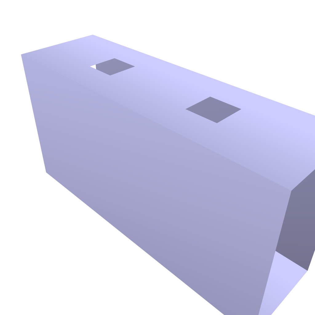
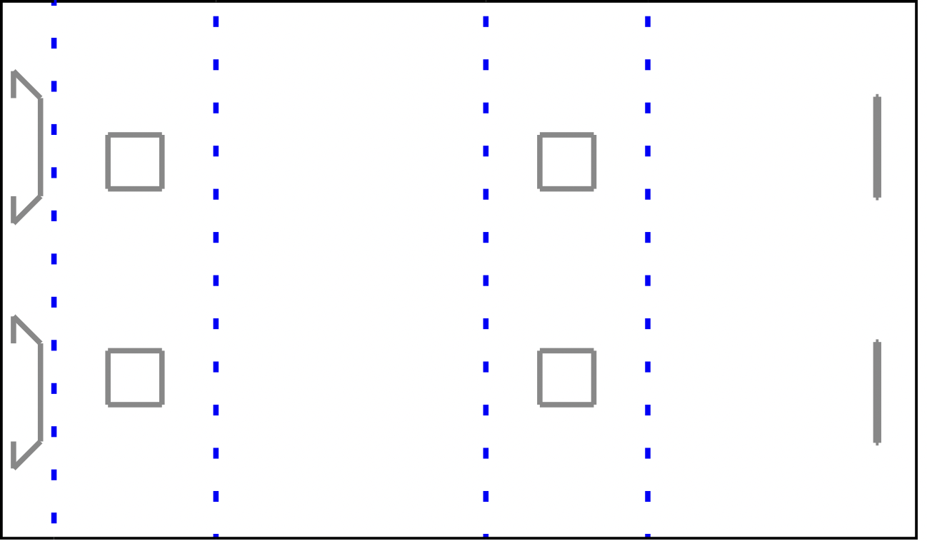
This body would allow for four motors to be able connect to the wheels outside of the rectangular prism body.
Aside from this, I also continued to design more robotic components in RoCo. Two of these components were a decagon 3D wheel and another body that used trapezoids and isosceles triangles. These designs were more advanced as the faces had many more connections and the angle for connections were much harder to compute.
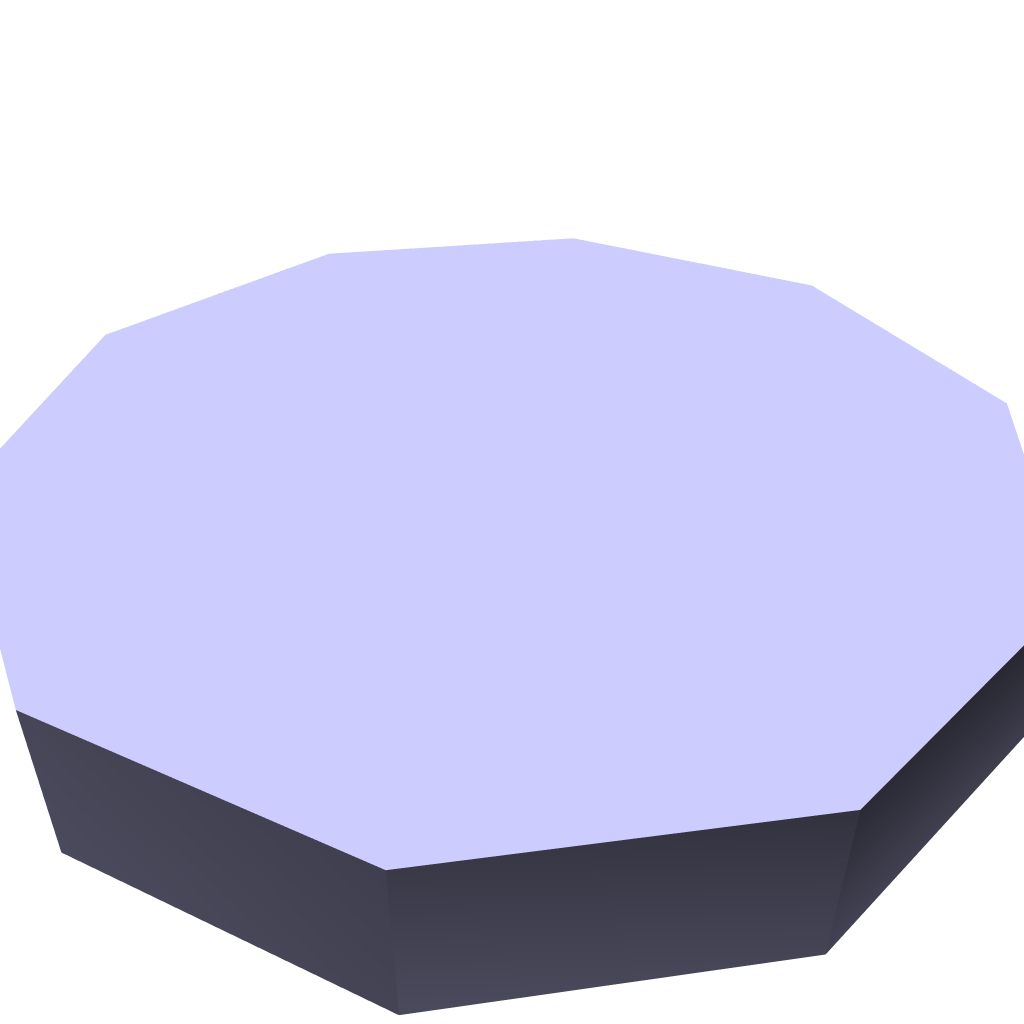
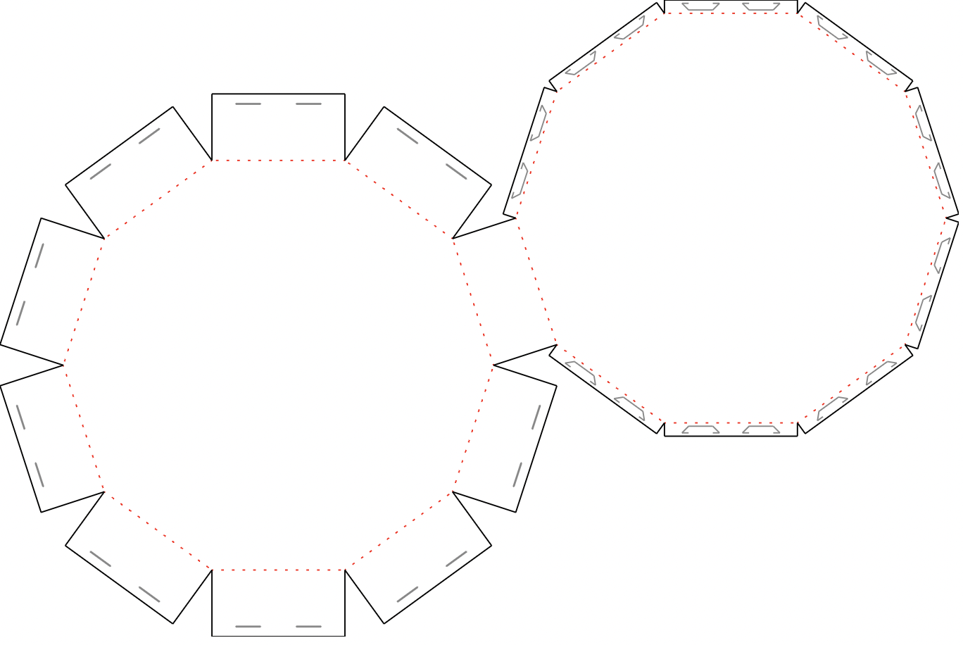
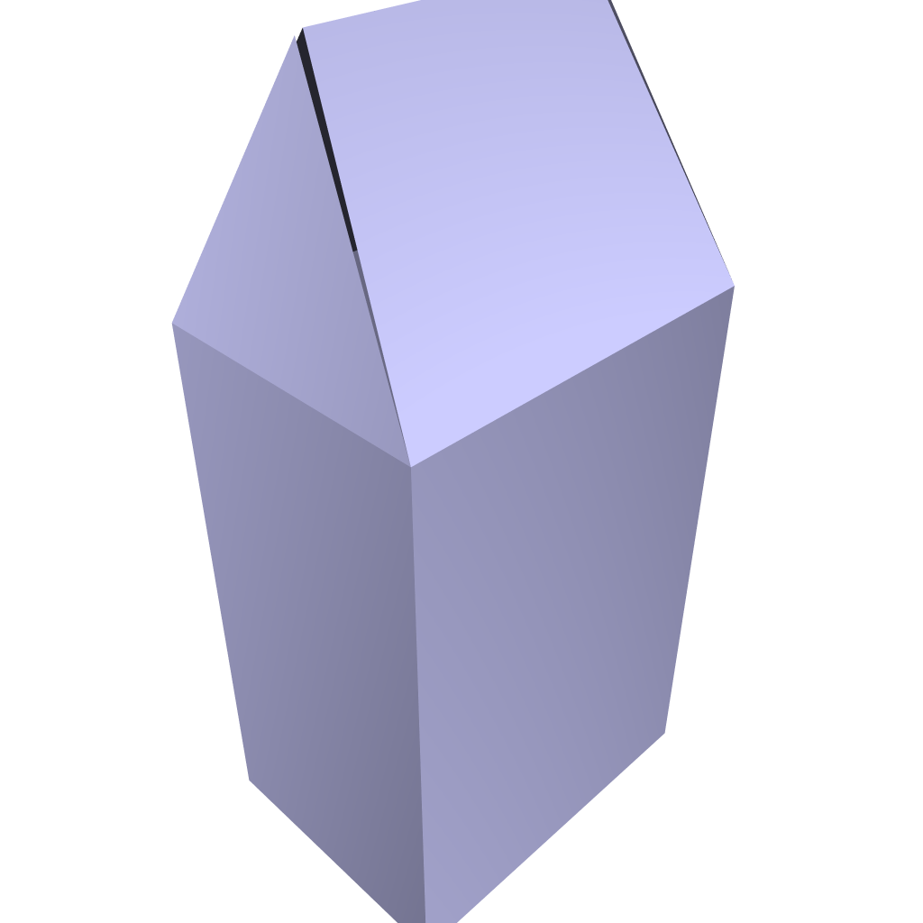
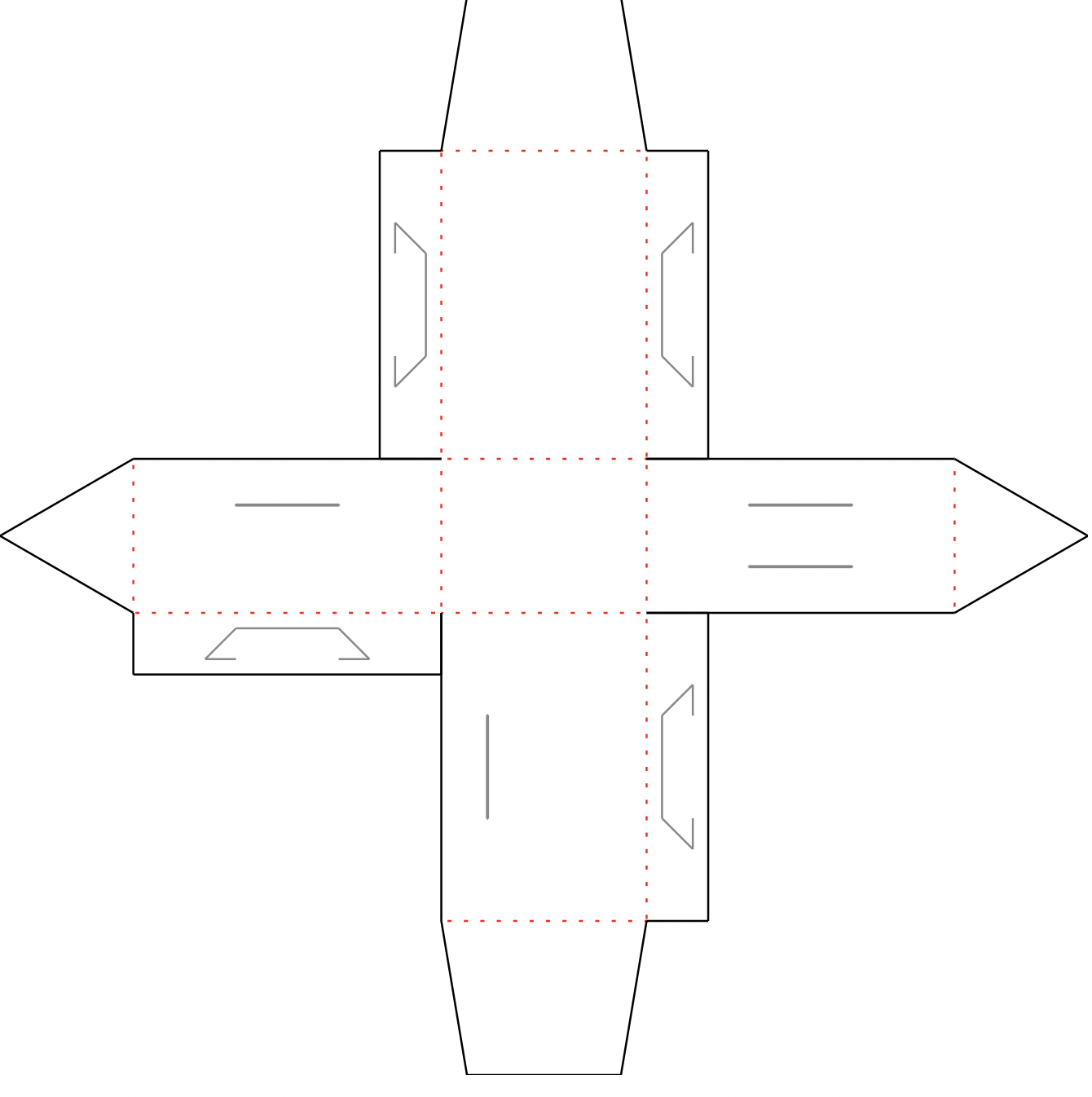
Now, I need to fully customize it and ensure that my microcontroller and wires can all fit well while taking into account weight and weight distribution for the robot. Since I am using thin materials, this is a very important aspect. Then, the next step is to add everything together, the customized modular components in RoCo, electronics, and microcontroller software, to produce my first functional ground locomotion RoCo robot. If I get this to go well, I will reiterate this process of buiding more modular components, customizing them, and connecting them with electronics to demonstrate a wider range of capabilities.