Hi everyone! I'm a new postdoc with LEMUR, and I'll be working on modern tools for circuit board level electronics design.
So that's a lot of words, let's unpack that. Modern board design tools (like KiCad) consist of schematic capture (drawing the schematic) followed by layout (placing components of that schematic onto a board). The problem here is that this requires a lot of low-level knowledge (less friendly to novices) and involves a lot of manual transcription from reference circuits (and is inefficient for everyone). This paradigm has been with us since the 80s, but in the age of blazing fast computers and usable interfaces, surely we can do better?
That's largely the motivation for my PhD project (shameless dissertation plug if you want to read it), which aims to re-imagine schematic capture as a tool that supports device design, instead of simply a drawing tool. As a quick overview, Polymorphic (Circuit) Blocks (UIST'20 paper, GitHub repo) achieves this through a hardware description language (HDL) and by taking inspiration from software engineering concepts. So, instead placing symbols and connecting pins on a graphical schematic, one would declare blocks (representing components) and connect their ports (representing pins) in a textual HDL. The critical advantage of a textual HDL is the ability to support design automation - for example, enabling code to automatically compute the resistance in a LED-resistor circuit, to automatically size the inductor in a switching voltage converter, or to automatically choose fungible 'jellybean parts' (eg, resistors, capacitors) from a parts table. This allows parts to encapsulate the knowledge of experts, while presenting an interface that is much more accessible.
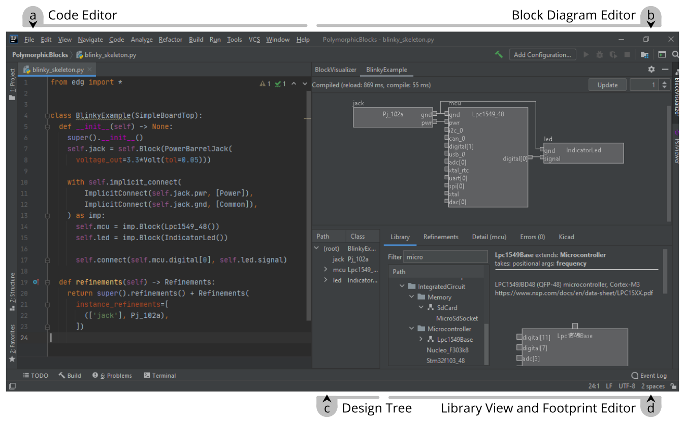
While powerful, an HDL is also a very different interface, so supporting tooling in the form of an IDE (UIST'21 paper; GitHub repo) are critical. This presents users with a block diagram style interface, but actions on the interface also generate into textual HDL, and users can arbitrarily interleave usage of the block diagram and text editing interfaces as needed for the particular task. The block diagram visualization can also help navigate, understand, and inspect a generated design, for example by showing automatically-derived values of components.
 The IDE interface showing the code and corresponding block diagram visualization for a 'hello, world' blinky device.
And none of this would be any fun if we didn't get any useful boards out of it, so (semi-)regularly making example designs has been a goal. The latest board is an USB source-measure unit (HDL, layout) - think DC power supply plus electronic load in one instrument, or a Keithley SourceMeter that doesn't cost an arm and a leg - and finished just as I was wrapping up at Berkeley. Over the past few weeks, I've been slowly bringing up this board, and it pretty much works!
 Perhaps the smallest source-measure unit. Thermal design needs a lot more work. I may or may not have accidentally sent a transistor into thermal runaway.
And in building that board, it's obvious this design system needs a lot of work, and this will be one of the driving examples going forward. For example, better support for array-like components (for example, analog switches) could enable an automatically generated and parameterized ranging circuit, while support for multi-pack devices could reduce costs and board area by using quad-pack opamps instead of 4x single opamps. And to be honest, while a HDL makes a lot of sense for a system diagram or highly parameterized subcircuits, it makes less sense for heavily analog subcircuits where the diagram is critical. One idea would be to support representing a block as a KiCad schematic - to not reinvent the wheel for graphical drawing tools and symbol library - and provide integrations with the rest of our system.
While this post was largely an introduction, future posts will dive more into the technical progress, like data model upgrades. Development continues in the open on GitHub, and feel free to join in the discussion on new ideas on the issues board.
As an open-source project, I'm always looking for collaborations! If you're an undergrad at UCLA with a programming or electronics (or some other vaguely-relevant) background and this sounds interesting as an undergraduate research project, please reach out to me (richardlin at g.ucla.edu). Otherwise, if you're interested in using or contributing to this system, or are also doing research related to board-level electronics design tools, I'd also love to hear from you!