Quick Reminder:
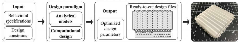
Goal: computational design and fabrication of corrugated mechanisms from behavioral specifications
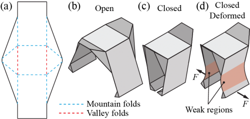
We studied double layered corrugation mechanism. The purpose is to increase stiffness in foldable structures. We also provide a simple model for optimial design based on maximum stiffness requirements.
SCF Reviewers' Comments Summary
1. Model explanation.
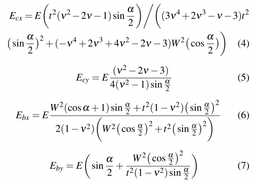
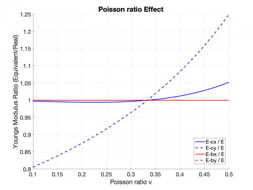
(1) When alpha = 180 degree, Young's modulus should be same along x and y direction. However, this is not the case using the equations I derived.
Answer: The method I used from two existing papers best approximate the stiffness matries into mathematical expression. The method gives results that gives certain errors to the results.
I set alpha = 180 degree and got the following equations. I plot the ratio between calculated Young's Modulus and that of the material. Results show bending Young's Modulus at alpha = 180 degree match the expection. However, compression Young's Modulus at alpha = 180 degree varys as functions of poisson's ratio. But when 0.25 < v < 0.4 (range for regular solids), compression Young's Modulus is within 10% error.
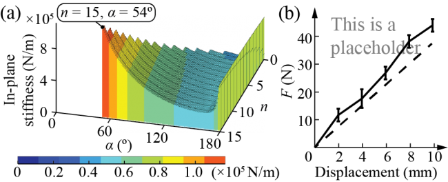
(2) The more the corrugations, the higher the stiffness. So why not use infinite amount of currugations.
Answer: The amount of currugations is related to other geometry constrains, such as the thickness of the whole structure, the maximum fabrication dimension and etc. So our approach can give people the optimized (maximum stiffness) design WITHIN CONSTRAINS.
(3) There is not need to use coding for the model.
Answer: The code does not only do the calculation, it also give us the best design parameters AND automatically generate the foldable pattern that can be directly used.
2. No validation to the proposed model.
This will be addressed by conducting corresponding experiments.
3. Lack of "limitations" in conclusion section.
I will add one paragraph to the conclusion section discussing the limition of this corrugation mechanism.
Experimental plan:
The tests listed on this page will take approximately one week to finish, if time is used efficiently with >10hr/day.
Model Validation
1. Young's Modulus of the membrane sheet
Sample size: N = 3
Result will be presented in one figure. But due to the page limitation, it will probably be indicated in text (one sentence).
2. Stiffness Model Validation (in Modeling section)
(1) Shape: will use rectangular, since it is easier to fabricate
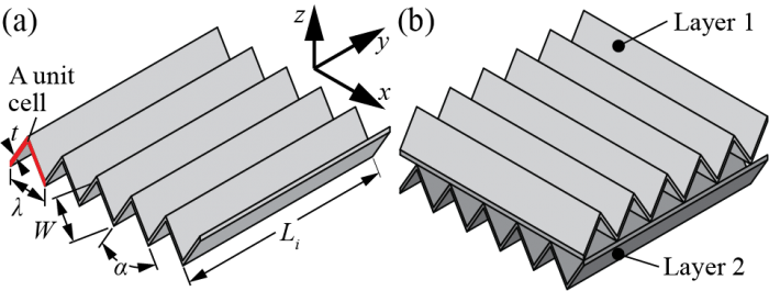
(2) Parameters: the stiffnesses (compression and bending stiffness) are both functions of n (number of creases), W (width of each unit plate), and alpha (folding angle).
K = f (n, W, alpha)
(3) Test sample of 3 to get mean and standard deviation.
(4) Plot: two plots (one for compression and one for bending), ?? tests in each plot.
Questions:
(1) How do we choose n, W and alpha to make it representative? --> How to prove the stiffness model works for different combinations of parameters?
Possible answer: four sets of samples, (n1, W1, alpha1), (n2, W1, alpha1), (n1, W2, alpha1), (n1, W1, alpha2). These will also give us different sizes of samples.
3. Case Study
(1) Validation of the spring model, part 1: compression test
Shape: Circular (Same as the corrugated wheels)
Dimension: D= 100mm, t = 25mm
Sample size: N = 3
The results will look like this:
(2) Validation of the spring model, part 2: bending test
Shape: Squares (Same as the corrugated gripper)
Dimension: 100mm x 100mm x 25mm
Sample size: N = 3
The results will look like this:

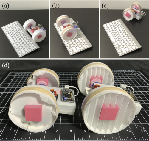
Case Study
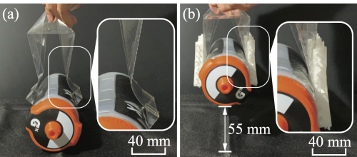
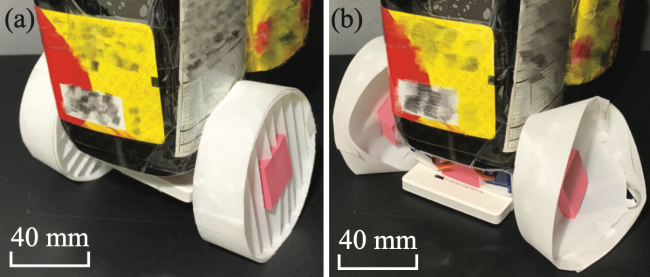
1. Car demos in case study need to be "upgraded". The soy sauce bottle will be replaced by the manuel material tester.
2. Car wheel compression demo may be deleted from this submission, due to the page limit. I will try to leave it in the paper.
3. Gripper demo. I would like to keep this demo in the paper. There should be no extra work needed for this demo.