New Capabilities:
Robot Compiler, RoCo is a sophisticated origam robot generator that a user can define how to cut and fold paper, and change design parameters with ease. I have been working on to export roco generated robot designs into physics simulation software, Webots, so that the user can further evaluate the robot design in a simulation environment.
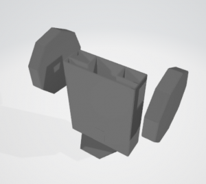
As a first step, a new function was added to convert a roco 3D robot geometry information into a generic file format, wrl, that Webots uses. Such geometries were converted into a Shape node piece by piece, i.e. a body, tires and exported as .wbo, a file format that Webots store robot information. The following image is an imported origami robot (Paperbot) using a .wbo file from RoCo.
Secondly, devices have been added to the roco so that Paperbot includes mechanical and electrical components information such as servo motors and sensors. Device information is stored in a library and users can swap between different sensors by changing parameters.Here are several test results of the different Paperbot designs running in a Webots environment. The robot is going to a target position (represented as a red bar) using a PID controller (Credit: Chang).Testing videos of exported .wbo.
Standard size paperbot (x10 speed)
From left to right: Double the width, Double the length, Double the height, Double sized paperbot. All in x10 speed.
In some rare case, the robot was trapped at the edge of the hill.
 (x5 speed)
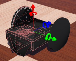
It is possible to have two of the same device in the same robot, such as servo motors. The following images are an example of two GPS installed on top of the Paperbot in different positions and orientations.
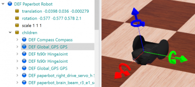
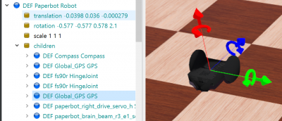 .
.
Another capability added to RoCo is a new tire shape design component. This new tire can adaptively change its design based on a user specified tire thickness parameter. For instance, if the thickness is none-zero, then it generates a folded nonagon tire which was created based on Jill's tank tire as shown
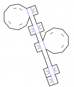
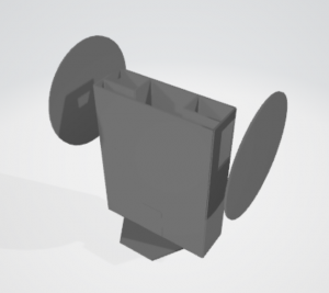
If the thickness is zero or not specified with a user, then a disk design is used alternatively.
Upcoming Updates:
- Programmer friendly device connection definitions
- Adaptively change the paper cutouts based on device geometries
- Add support for .obj file with all devices shapes and folded paper
Currently, a connection between a device and paper needs to be explicitly defined by the user along with geometric connections. For instance, a tire needs to be mounted to a servo horn and the servo device needs to know what is driven by it. We will introduce a new device anchor port that defines both geometric and kinematic connections. This not only simplifies the designing process, but also allows us to validate if a connection is feasible or permitted.
Paper cutouts are defined as a decoration on paper such as a hole for microcontroller pins. However, such cutouts should depend on the device shape rather than predefined in each paper part design. The current RoCo framework requires us to predefine cutouts in advance on paper, but ideally, a deice anchor connection should create proper mounting holes wherever attached automatically.
RoCo supports two 3D mesh file format, .stl and .wbo. STL is a generic and simple 3d mesh file format commonly used for 3d printing. However, it does not carry parts information, material, appearance, or design units. The webot node file, .wbo, can include those and device data, but it requires Webots installation to open it. The object file, .obj, can include parts and appearance information and most CAD and a 3D viewer can open it.
Known Issues:
- Webots warning that mesh is too complicated This is a common issue if the mesh is not optimized well such as when we import a CAD file into Webots. One solution is to approximate the geometry with Webots provided shape definitions such as a cylinder or box, but this will limit the generality of RoCo. Currently aside from a minor physics issue shown above, we are seeing reasonable simulation results. Hence, the existing RoCo meshing mechanism is sufficient for our needs at this moment.
- Body mesh self-intersections When generating a 3D mesh, a user-specified paper thickness is applied, which causes a self-intersection at a folded edge. RoCo does not take a union of the mesh, but this type of self-intersection is unlikely to cause issues as long as they are all a part of one body. If a user is to 3D print the robot using .stl from RoCo, slicing software needs to fix the mesh.
Future Works:
- Adding non-geometric and non-kinematic connections
- Parametric coding, a robot controller
An actual paperbot has more assembly than just mechanical connections. Electrical connections have to be done properly to run servos and read sensors. Connected servos should have a proper ID so that an algorithm can control them. Such connections and relationships are not included in RoCo yet, but they are vital to generate a feasible robot design.
A controller code is necessary to run a robot and it has to be modified depending on the robot configuration. If the robot has four wheels instead of two, the controller should change the outputs. Sensors can use different filterings, which would be a parameter for the code. Device IDs and IDs used in the controller should match properly, otherwise, the algorithm cannot receive sensor readings. The robot controller type needs to be selectable such as python for Webots and C for Arduino.
However, due to the scale of additions we have to conduct we set these to be future works.