Goal 1: Get RoCo-designed robots to work well in Webots
Problems:
- RoCo generated .stl file is for presentation, the parts are considered as one solid body, which means there will be no rotational/translational parts simulated in Webots.
- How to get RoCo generate files that can differentiate the assemblies?
- How to add axis (joints) and motors?
Potential solutions:
Two tutorials that may be useful:
Summary (Potential solutions, need validation):
- In RoCo, Save robot assembly into .obj file.
- In Blender software, convert .obj file into .wrl file.
- In Webots, import .wrl file. There should be several "Shape" representing different components in the robot assembly designed from RoCo.
- In Webots, add a new base node (robot), move all "Shape" into "children" under the new base node (robot).
- (Optional) In Webots, save the new base node (robot) into .wbo file, for future multi-agent / SWARM applications.
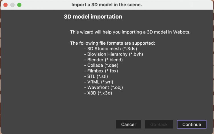
Here are the file format that Webots can import. I assume if we can export RoCo design into one of these format (also makes discrete component move independently), we can import directly into Webots.
Following last step, here is a summary (Potential solutions, need validation):
- TBD
Intermedium results
1. Import .stl robot car and drop it in Webots from different height. {To learn how to use Webots?}
- Drop from 0.05 height
- Drop from 0.25 height
- Drop from 0.35 height
Problem:
- Car passed the ground.
- Car wheels in the ground at the end for some cases.
Potential reasons:
- Bounding properties are not set correctly (currently approximated to simple shapes).
- The wheels are too thin to be captured (currently using paperbot design).
- It may be necessary to manually add a ground.
- Contact properties are not set correctly.
Tryouts:
- Different bounding types, rect, cylinder, sphere, etc do not work well, too much simplification. Looking at the 'meshing' on the robot car, it should be correct using the current settings.
- Using 3mm plywood robot car, same/worse simulation results.
- Based on a little research online, "Grounds can be defined using the Plane or the ElevationGrid primitives." So I manually added a ground using plane.
Well, same behavior, sad....
- Here is a description of how to set up contact properties. Well, I changed bounce from default 0.5 to 1. Well, it still does not look correct.... I will keep debugging ...