Objective:
- Find a way to map 3D gesture geometry to 3D object geometry
- Find a set of parameter to represent 3D geometry for the mapping
The reason to use parameters to represent, pass and map 3D geometries:
- The number of parameters is limited (compare to i.e. vertex number, mesh number, etc)
- and thus would be a reduction in DoF (since the main challenge in the pipeline is to match DoFs), to reduce the information flow
- and still extract the most important and necessary information from 3D geometries
- which could also be important to constrain the demands on computing power
Parameter of planes
The plane here is not exactly the same with a general geometrical plane with infinite size, which can be determined by the following basic methods:
- Three non-collinear points (points not on a single line).
- A line and a point not on that line.
- Two distinct but intersecting lines.
- Two parallel lines.
The plane geometry in our flat-pack objects can be understood as a surface of wooden/paper component of the design object, therefore, such plane has limited size and (sometimes irregular) shape.
It is essential to define/identify/determine a plane of the design object in the design process, because:
- it would make it clearer to identify a targeted plane for further modification
- (even though it may or may not be directly selected by the user, the system could still make use of the extracted information about targeted plane from user gesture to process other design commands)
We propose several sets of parameters to represent a plane, though each set has its limitations:
- Method 1:
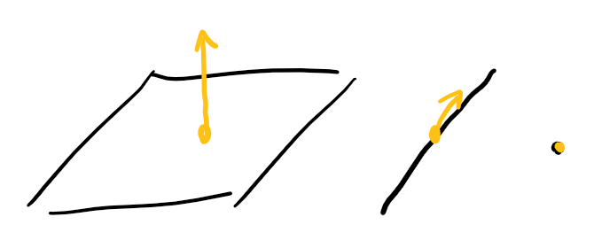
- center position (center of gravity) of the plane in 3D
- normal direction of the plane
- Method 2:
- a point on the plane that is closest to the center of gravity of the plane
- normal direction
- Method 3:
- three (or more) key points on the plane
- normal direction
Here are some examples to show the limitation of these methods:
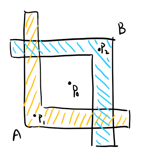
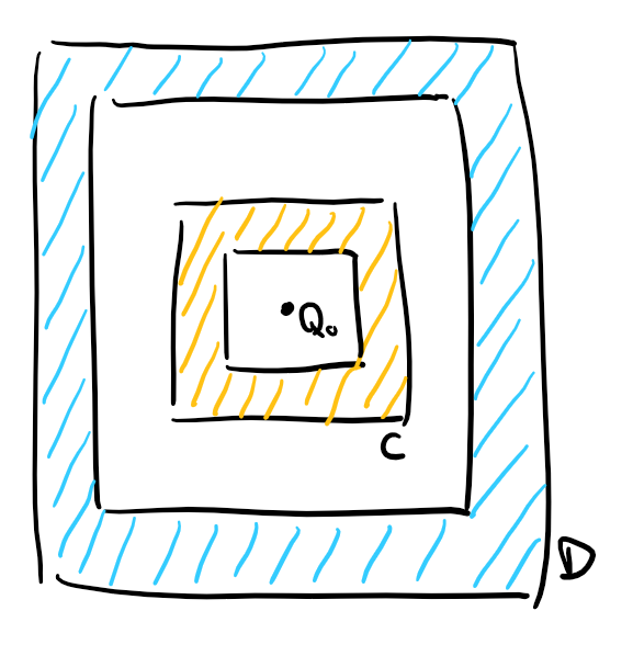
For Method 1, the center positions of plane A and B are possible to be the same, both at point P0; and they also have the same normal direction, therefore the parameterized representation of plane A and B are exactly the same, thus the system or the user would not be able to identify which plane they want to select and modify while keeping the other remain the same. The situation is the same with plane C and D.
Though the example of plane A and B is mostly just an explanation for the limitation of the method and not practically likely to happen in our flat-pack design object, because if there are two components have crossed faces, they would be combined to one whole plane.
And the problem of hollow faces as seen in plane C and D though could be possible, it is not how the backend compiler creates hollow faces for now. In our current existing object library, rocker chair has hollow faces which are compiled from small triangular meshes for stl file, so the problem would not yet reflected if use Method 1 and current object library for demonstration.
For Method 2, the determinition of "closest point to gravity center" is ambiguous. There could be more than one point that is closest to the gravity center, and maybe none of them are the most intuitive representation. For example, the ideal representation point of plane A and B might be point P1 and P2, but the closest point to P0 is on the arm of the "L" shape. And in plane C and D, the four edges of the hollow square shape is in the same distance to point Q0. But overall, Method 2 might be more generally appropriate because our backend compiler prevents two planes to be both have same normal direction and occupy same space position (otherwise they should be the same plane), therefore, there should not be two planes have the same representation with Method 2.
For Method 3, it is even more ambiguous to determine what is key point for a irregular plane. In our case where there is no curve for any plane, the key point can be defined as the turning point between edge of lines on the plane. But the problem with this definition is that the number of key point could vary greatly among planes, and therefore this method may not show the advantage of parameterized representation (that reduces DoFs).
Therefore, for ease of implementation and demonstration of the whole system without doing too much harm to the function, we are going to use Method 1 for now, which should not be too much trouble if we need to transfer to Method 2 in the future work.
Parameter of lines
- For infinite line:
- a point position on the line
- direction
- For finite line:
- the point positions of two ends of the line
Since the objective is to map 3D gesture geometry to 3D object geometry, it is easy to acquire the location information of a finite line from the object, but the length information is of no use for gesture, because when a designer indicate a line with hand gesture, the length information is usually omitted. So after receiving end point positions of lines, the system will store line information using the center position of the two end points and one arbitrary direction (among the two directions that are opposed to each other in 180 deg).
Parameter of points
- position of the point
Conclusion
The parameters that are used to represent 3D gesture and 3D object geometry are listed as following:
- plane:
- position of center of gravity (3 DoF)
- normal direction (3 DoF)
- line:
- center position of two end points (3 DoF)
- direction (3 DoF)
- point:
- position (3 DoF)
(Updated: 08/24, 09/08)