There are three steps I will take in order to implement this design tool:
Step 1: Verify I operate correctly in FEA (Solidworks Simulation). In order to do this, I will use some existing numerical solution and/or analytical solutions to find out critical buckling load. Then I will apply this critical buckling load to FEA analysis. If the resulting buckling factor (called safety factor in Solidworks Simulation) equals to 1, it means results from existing solutions match FEA result. Then I will continue to the next step.
Step 2: Develop and evaluate plane stress. We first need to convert loads on edges to stress distributed in plane. Plane stress analysis in our design tool will result in stress distribution (von mises stress) in plates under in-plane loads. In FEA, I will conduct static analysis with in-plane loading. Stress results will be used to compare with that obtained using our design tool. If results match, or at the same magnitude, or have the same trend, I will continue to the next step.
Step 3: Develop and evaluate plate buckling. Stress distribution from step 2 will be used to calculate work load energy in buckling analysis, in order to be used on principle of minimum potential energy calculation. The buckling analysis will be implemented in my design tool, and converted into an eigenvalue problem. The eigenvalue will be the buckling factor. If it is greater than 1, it means no buckling happens in plate; if it is small then 1, it means the plate buckles; and if it is 1, it means we just find critical buckling load. This buckling factor will be compared with that obtained from FEA buckling analysis. If they match, it means this subproblem has been satisfactorily solved.
Step 1: Verify FEA operations using existing analytical approach
I tried to verify my FEA operation using the following steps:
- Find out existing analytical solutions and numerical solutions. I decide to use 5 examples, as presented below.
- Calculate theortical critical buckling load from those solutions.
- Build models in Solidworks Simulation, apply correct boundary and loading conditions.
- Run buckling analysis, check results (safety buckling factor).
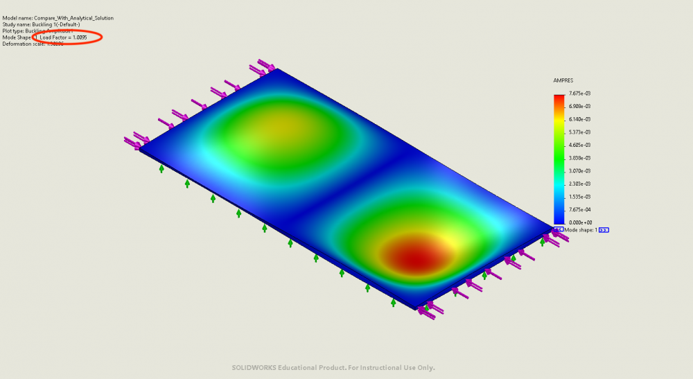
Example 1: SSSS
- Shape and dimension: rectangular 100mm x 50mm x 1mm plate
- Boundary condition: simply supported on all four edges
- Loading condition: uniaxial compression on shorter edges
- Mechanical properties: E = 3GPa, v = 0.25
- Critical buckling load from analytical solutions: 4212N/m along the short edges, or 210N on short edges or 84240 N/m^2 on short edges. Also there should be two half-waves across lengthwise direction and one half-wave along widthwise direction.
- FEA result: buckling factor of safety = 1.0095. Results can be found bellow:
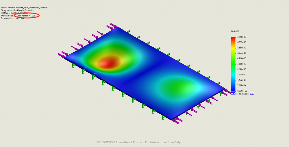
Example 2: SCSC
- Shape and dimension: rectangular 100mm x 50mm x 1mm plate
- Boundary condition: simply supported on two short edges, fixed on two long edges
- Loading condition: uniaxial compression on shorter edges
- Mechanical properties: E = 3GPa, v = 0.25
- Critical buckling load from analytical solutions: 7340N/m along the short edges, or 367N on short edges.
- FEA result: buckling factor of safety = 1.025. Results can be found bellow:
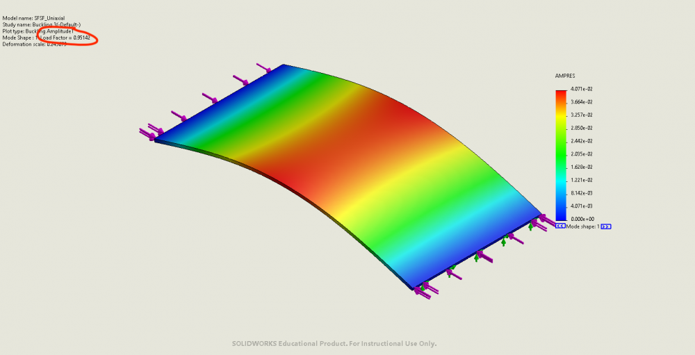
Example 3: SFSF
- Shape and dimension: rectangular 100mm x 50mm x 1mm plate
- Boundary condition: simply supported on two short edges, free on the two long edges
- Loading condition: uniaxial compression on shorter edges
- Mechanical properties: E = 3GPa, v = 0.25
- Critical buckling load from analytical solutions: 13.16N on short edges.
- FEA result: buckling factor of safety = 0.95. Results can be found bellow:
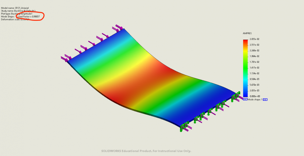
Example 4: SFCF
- Shape and dimension: rectangular 100mm x 50mm x 1mm plate
- Boundary condition: simply supported on one short edge, fixed on the other, free on the two long edges
- Loading condition: uniaxial compression on shorter edges
- Mechanical properties: E = 3GPa, v = 0.25
- Critical buckling load from analytical solutions: 26.3N on short edges.
- FEA result: buckling factor of safety = 0.9884. Results can be found bellow:
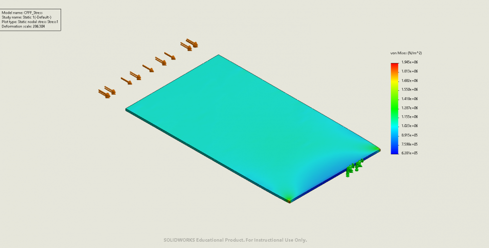
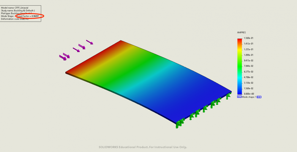
Example 5: CFFF
- Shape and dimension: rectangular 100mm x 50mm x 1mm plate
- Boundary condition: fixed on one short edge, free on the other three edges
- Loading condition: uniaxial compression on shorter edges
- Mechanical properties: E = 3GPa, v = 0.25
- Critical buckling load from analytical solutions: 3.29N on short edges.
- FEA result: buckling factor of safety = 0.9610. Results can be found bellow:
These five cases have been verified. These five cases will be used to verify plane stress results in the next step.
Step 2: verify plane stress analysis in our design tool
Same examples are used, with the following parameters:
- Shape and dimension: rectangular 100mm x 50mm x 1mm plate
- Loading condition: uniaxial compression on shorter edges
- Mechanical properties: E = 3GPa, v = 0.25
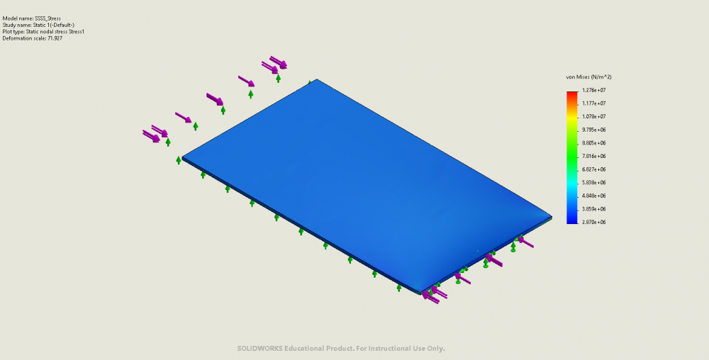
Example 1: SSSS
- Boundary condition: simply supported on all four edges
- Critical buckling load from analytical solutions: 210N on short edges
- FEA stress analysis results:
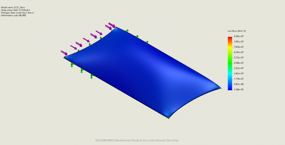
Example 2: SCSC
- Boundary condition: simply supported on two short edges, fixed on two long edges
- Critical buckling load from analytical solutions: 367N on short edges
- FEA stress analysis results:
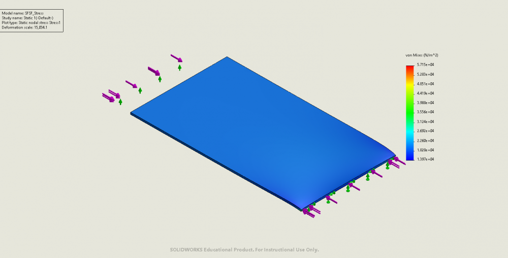
Example 3: SFSF
- Boundary condition: simply supported on two short edges, free on the two long edges
- Critical buckling load from analytical solutions: 13.16N on short edges
- FEA stress analysis results:
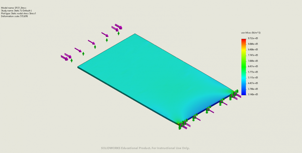
Example 4: SFCF
- Boundary condition: simply supported on one short edge, fixed on the other, free on the two long edges
- Critical buckling load from analytical solutions: 26.3N on short edges
- FEA stress analysis results:
Example 5: CFFF
- Boundary condition: fixed on one short edge, free on the other three edges
- Critical buckling load from analytical solutions: 52.6N on short edges
- FEA stress analysis results: