As mentioned in the last blog post, there are two steps in solving buckling problems
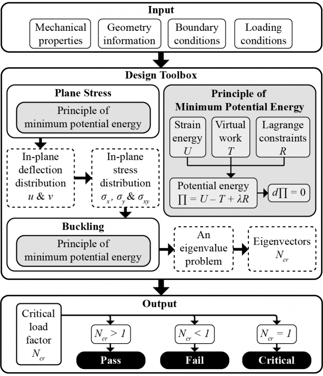
The first step is to calculate plane stress in the system. This step converts external load (in-plane load) into stress distribution in the plate, so as to be used later in the second step (buclking analysis)
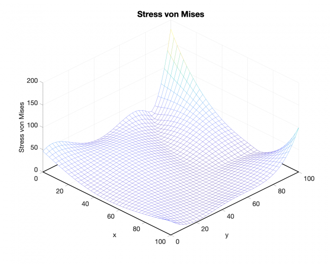
The following is the intermedium plane stress results -- stress and in-plane deformation
Why do we need stress distribution? Answer: The stresses throughout the plate are needed to simulate the area integral of the work of the loads.
The following results can be calculated directly from our design tool.
Example case:
- Young's Modulus: \(2.96 \times 10^{9}\)Pa
- Thickness: 1 mm
- Poisson Ratio: 0.37
- Dimension: 100 mm \(\times\) 100 mm
- Support: Simply-supported on all four edges
- Load: Compression on all sides, magnitude \(F = 10^{-3} N\)
Based on instinct, stress should be symmetric with respect to the center point. However, currently, the distribution does not look as expected. Working on debugging now. Maybe it is due to the calculation error, maybe it is the correct magnitude. Or maybe it is completely wrong.
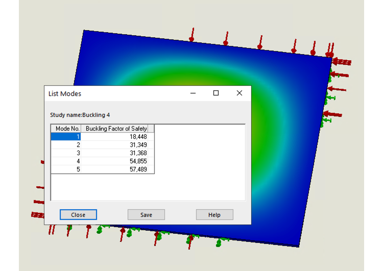
I am working on solving buckling in FEA. Currently I can get buckling amplitude. I am working on getting stress distribution across the plate, so that we can compare the results.
For now, i can calculate buckling factor from FEA, which we will eventually get from our design tool. Those two can be compared. As for now, the first step should be to make sure we can get correct plane stress results so as to continue studying buckling.