As part of generating an interface that automatically generates traces for pins connections depending on the user's desire, this past week I focused on learning KiCAD.
This open source helps you create a schematic that can then be turned into a PCB layout. I decided to get familiar on how to use it and learn more about creating my own components and then building a schematic of my own.
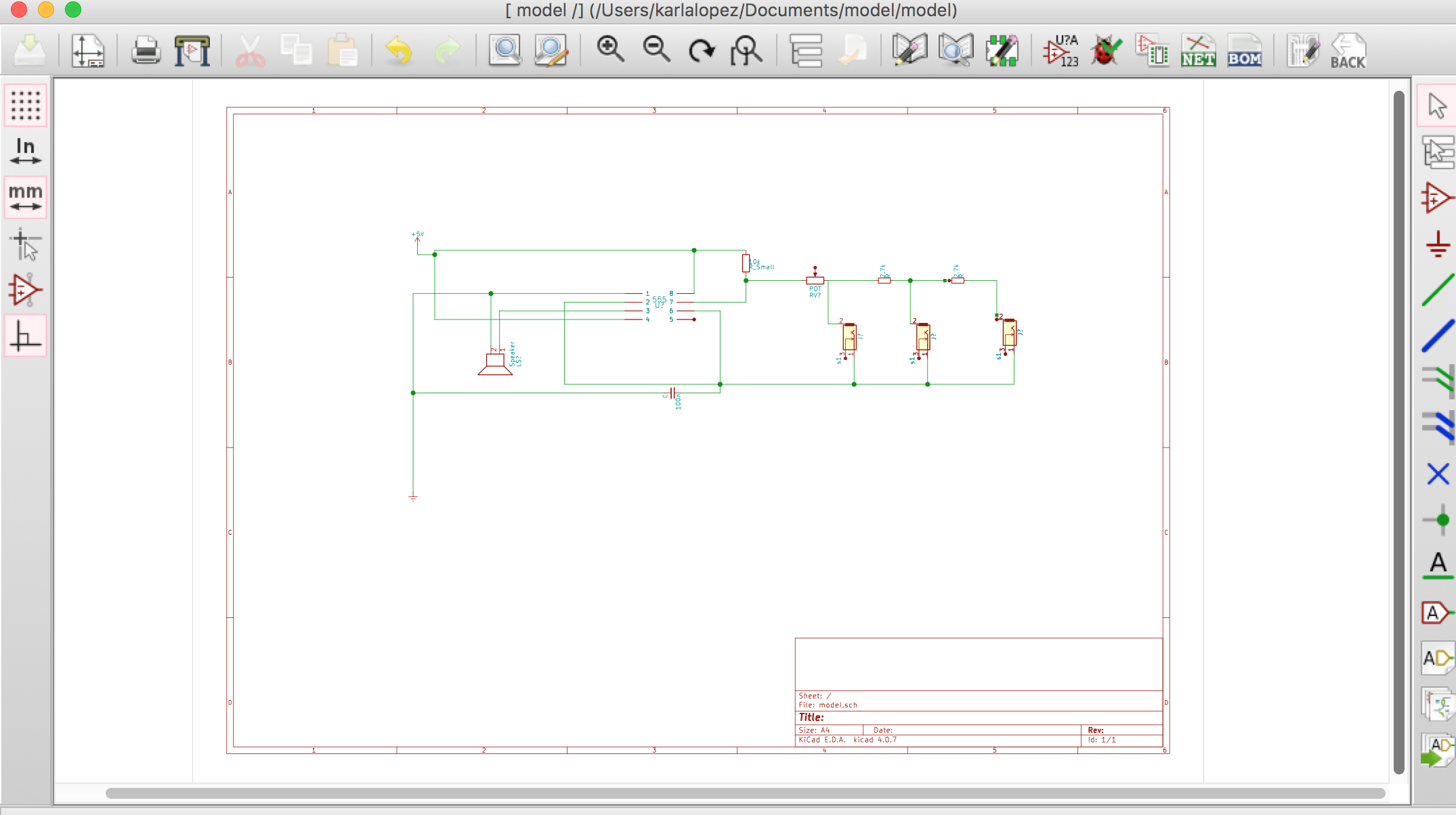
I decided to create a layout for the P.I.A.N.O. OPS project which consists of a speaker that is controlled by 3 pushbuttons and a 555 timer (along with resistors, a potentiometer, a capacitor, and a battery).
KiCAD's library does not have a 555 timer component so I was able to explore its capabilities and build one of my own. After I had created this component from looking at its datasheet, I was able to construct the schematic for the circuit.
Here is the final result:
 Getting familiar with this platform was very useful for future use since my future research will heavily depend on making automated traces.
As part of generating an interface that automatically generates traces for pins connections depending on the user's desire, this past week I focused on learning KiCAD.
This open source helps you create a schematic that can then be turned into a PCB layout. I decided to get familiar on how to use it and learn more about creating my own components and then building a schematic of my own.
I decided to create a layout for the P.I.A.N.O. OPS project which consists of a speaker that is controlled by 3 pushbuttons and a 555 timer (along with resistors, a potentiometer, a capacitor, and a battery).
KiCAD's library does not have a 555 timer component so I was able to explore its capabilities and build one of my own. After I had created this component from looking at its datasheet, I was able to construct the schematic for the circuit.
Here is the final result:
Getting familiar with this platform was very useful for future use since my future research will heavily depend on making automated traces.