This past week I used Rhino 7 to create .dxf files that can be used with the laser cutter and paper cutter (the CAMEOS). Designs were made within in the Rhino software and were manufactured using Vinyl Polyester as the material. (The plastic roll of material in the lab).
Before making a structure, I decided to manufacture the auxetic cells themselves and compare how the real life physical behaviour of the cells would differ from what was shown in the simulation last week.
The first auxetic cell that was tested was the following:
 This is the auxetic cell in a fully closed state.
 This is the auxetic cell fully deployed/how it "should behave"
One of the major observations before cutting out the cell was that the fully deployed state has the trianglular subcomponents joined by a basically infinitesimal connection which would not translate well into a practical sense. The first test was made using the .dxf file as if when exported from the rhino 7 software. Open doing this the pattern cut was simply a bunch of triangles. This revealed that that the .dxf files exported directly from rhino 7 would be "print ready" as is. using some of my intuition from mechanics I manually edited the cell design to still deform simillary, but have a segment of material that can still connect the triangular subcomponents.
The result was the following:

Deployed Design:

A possible reasoning as to why the auxetic appears to deform out of plance around the "hinges" (the place where cuts were intentially modified to not cut completely) is the choice of material. Since the material is very thin there is bending happening. Another possible explanation maybe that the cut out was really big which is amplifying this bending deformation. Nonetheless the auxetic cell displayed a similar behavior to what a deplyed auxetic cell looked liked within the rhino 7 software.
I unfortunatetly ran into more issue with the bass_cells, so I was unable to test those out. However, I plan on creating the following cell:
Undeployed:

Deployed:

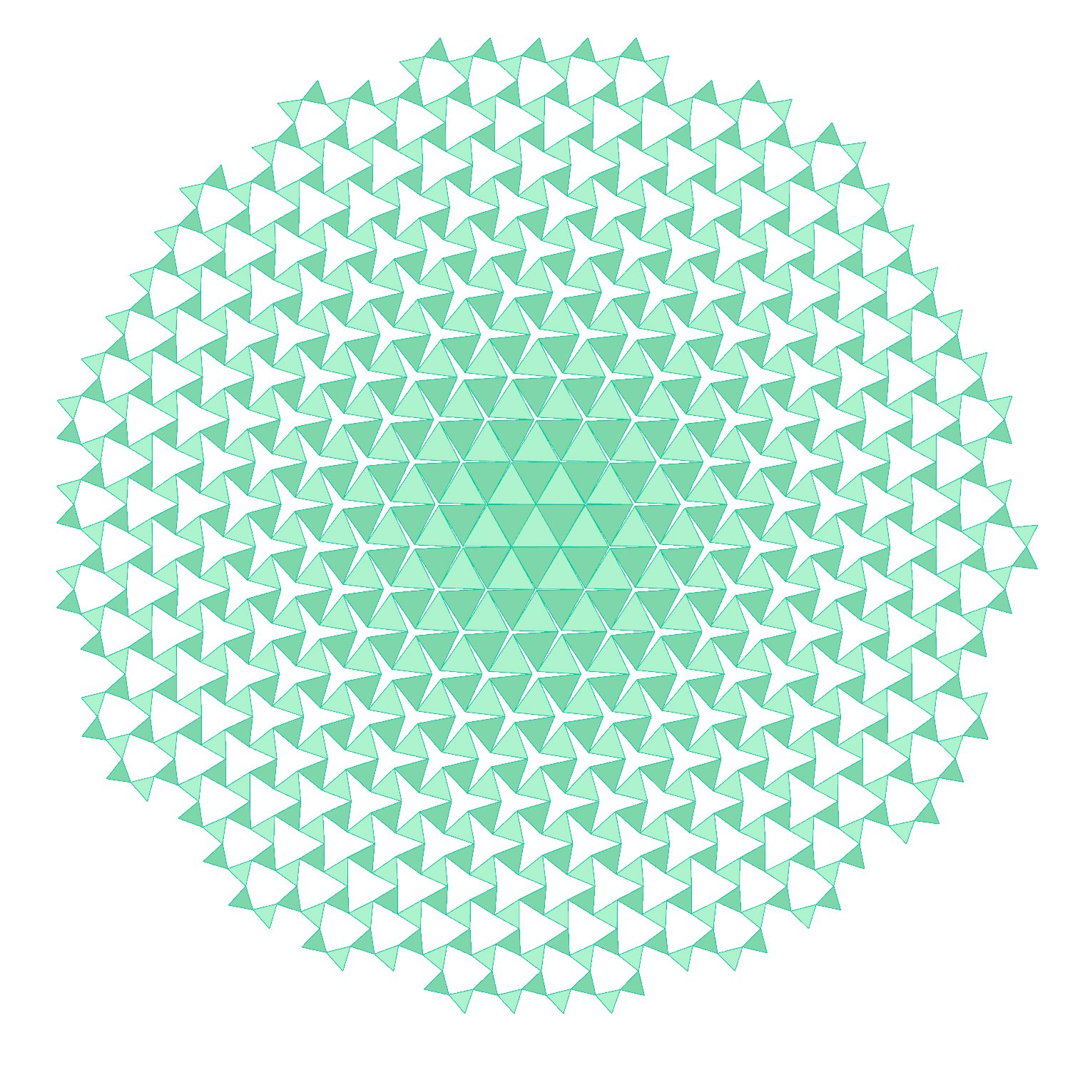
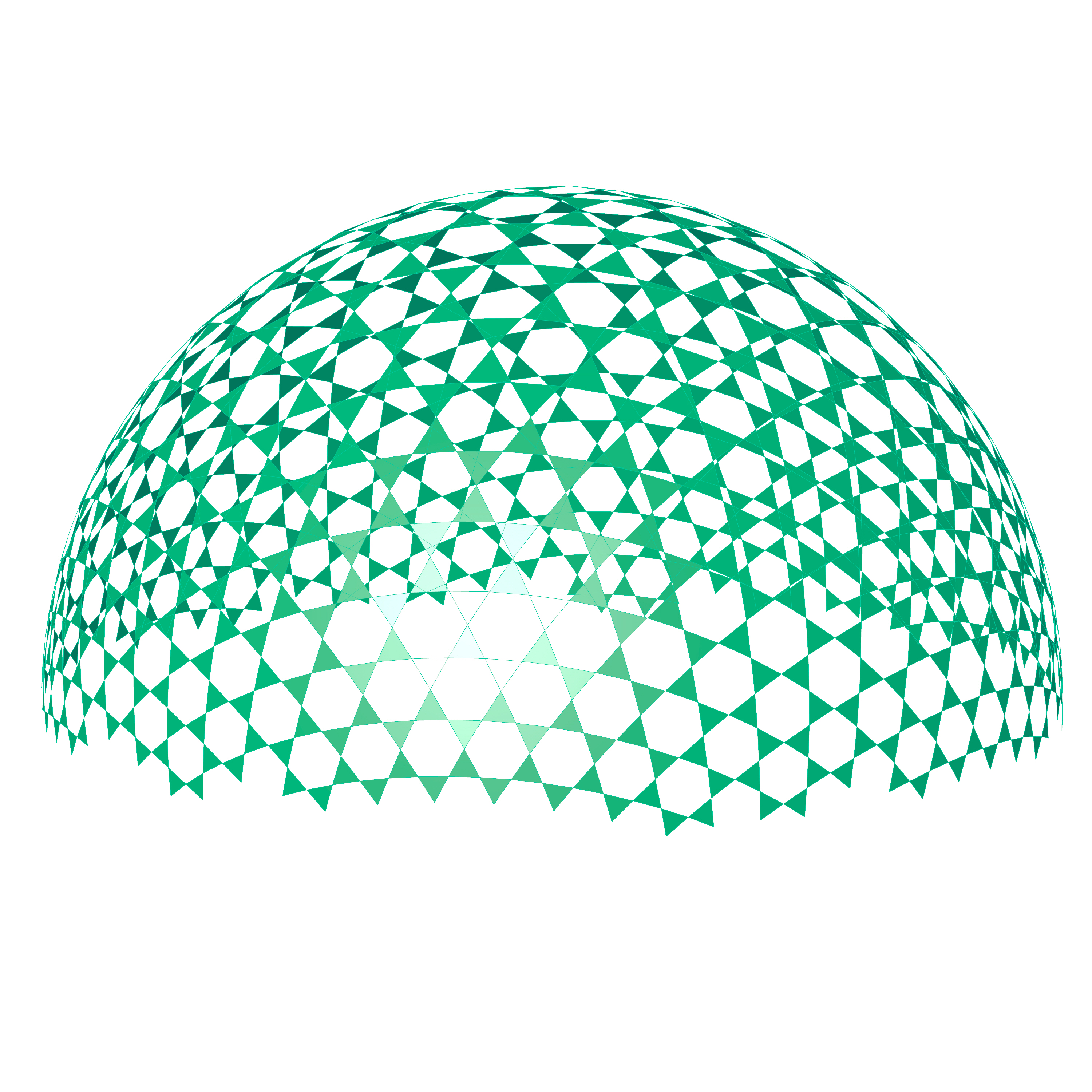
After testing the auxetic_cell I decided it was time to try and make a 2D to 3D deployable structure. I stuck with the half dome that was discussed in my previous blog post.
Cut lines:
Deployed Dome:
I used the vinyl polyester sheet once again since it had worked for the singular cell. The result was the following:
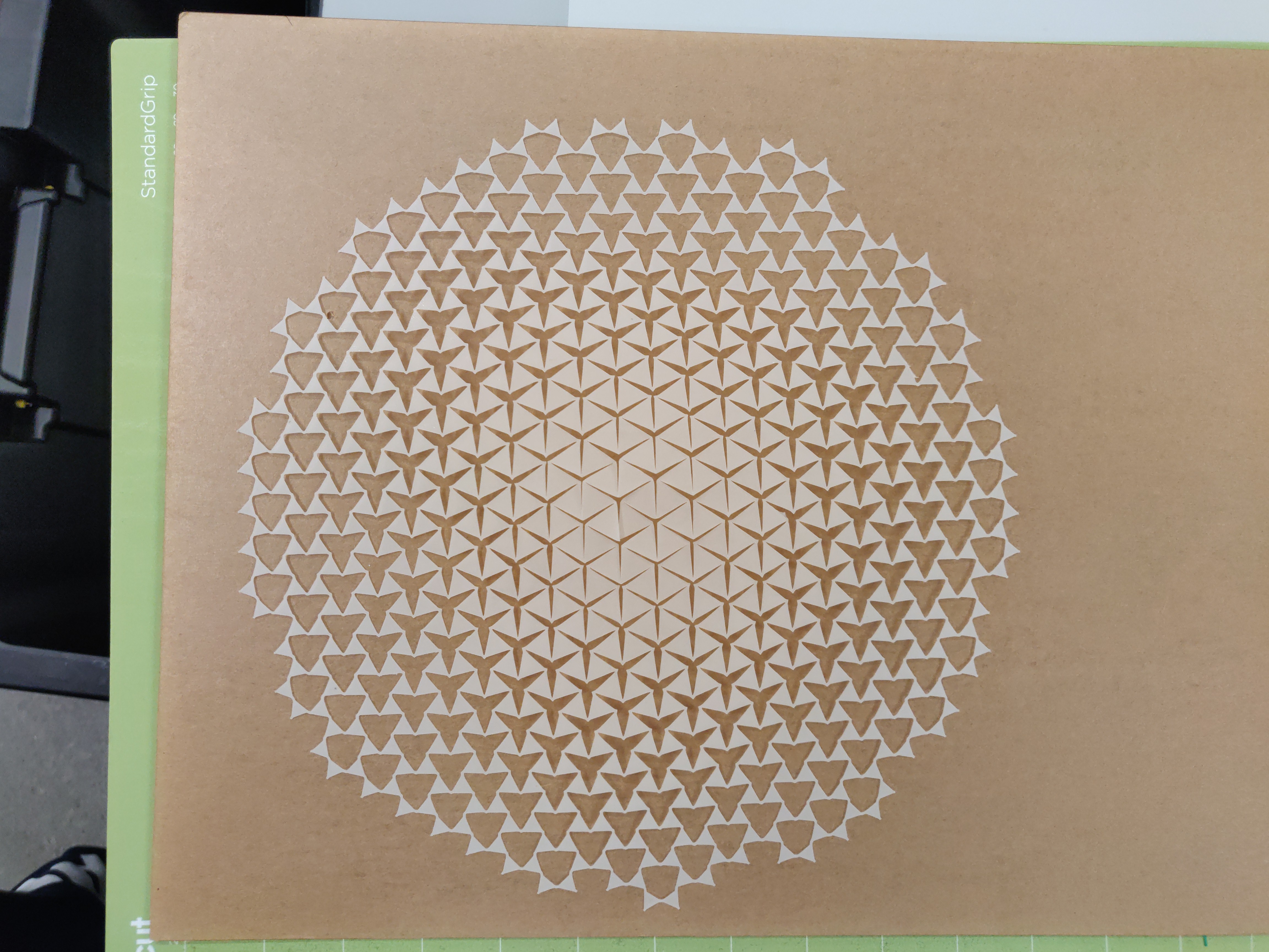
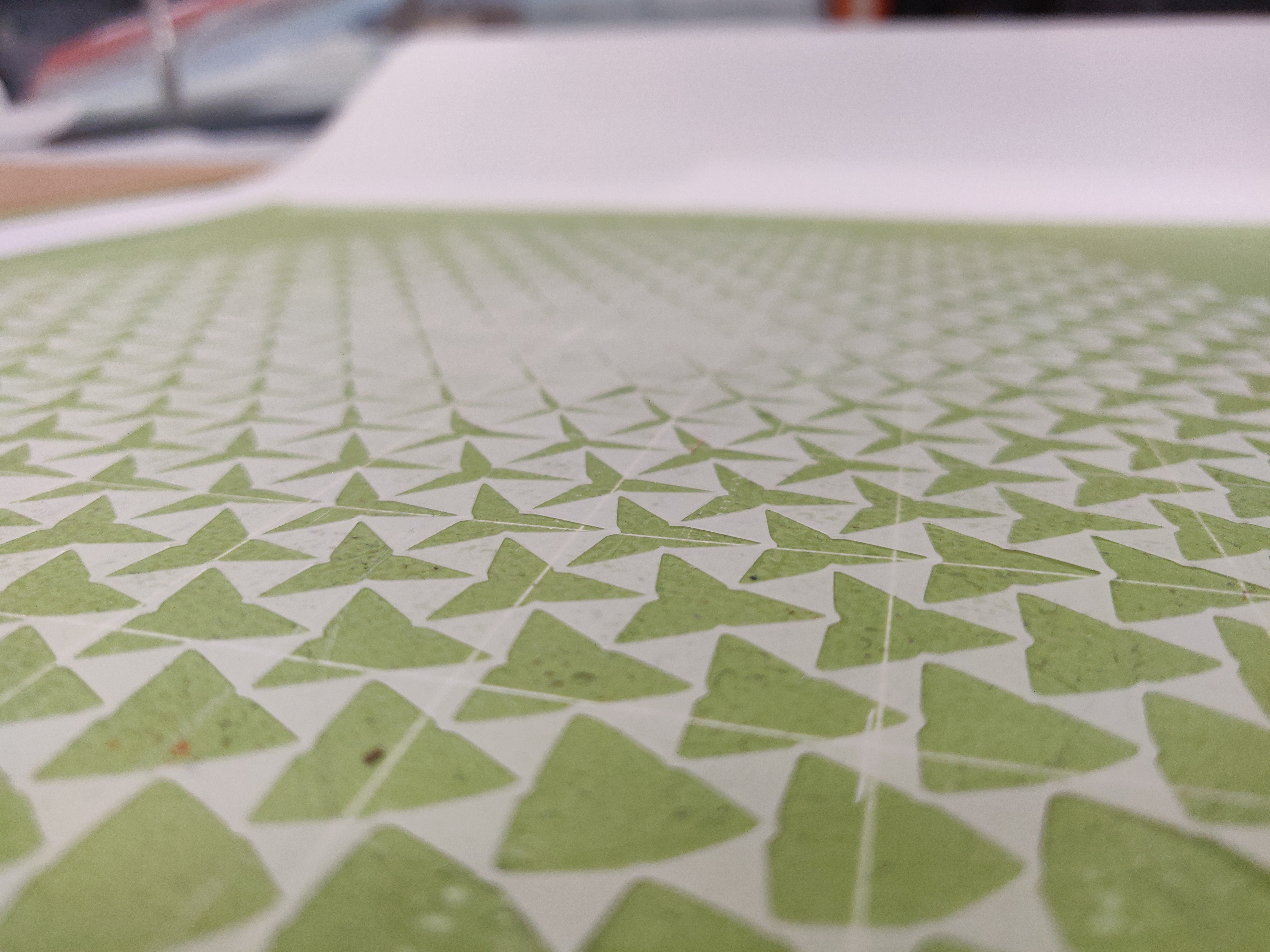
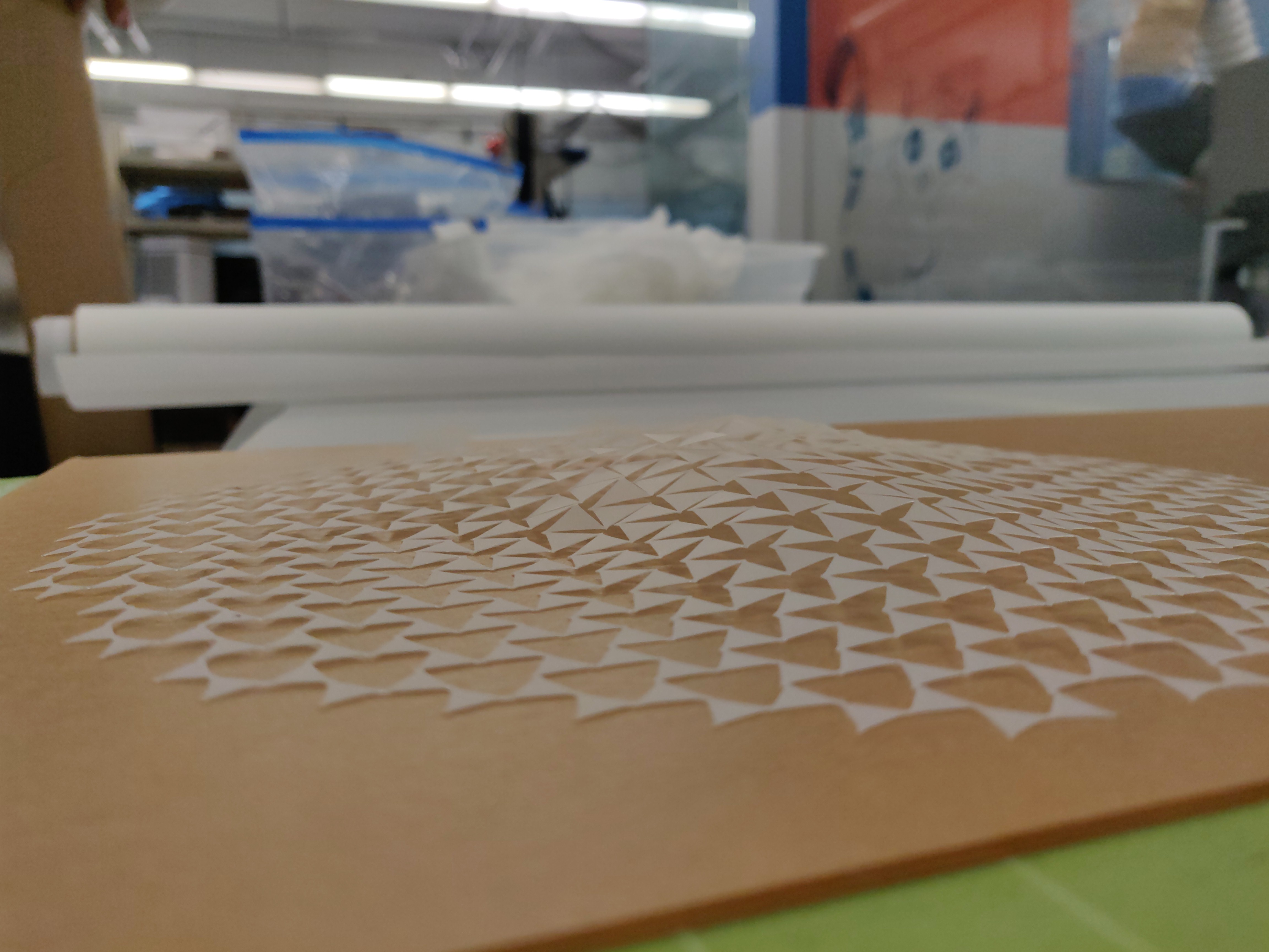
In the image it can be seen that the 2D design is composed of unit cells which have already been deployed to a certain degree will others are nearly fully closed. This variation allows for different ranges of deployablity when structure is actuated resulting in a "dome like" shape.
With relatively small applied force the structure begins to deform out of plane:
 .
.
After a considerable amount of force is applied the structure deforms more out of plane and has form that resembles more of a dome, but still not the complete dome shape as shown in the rhino 7 software:
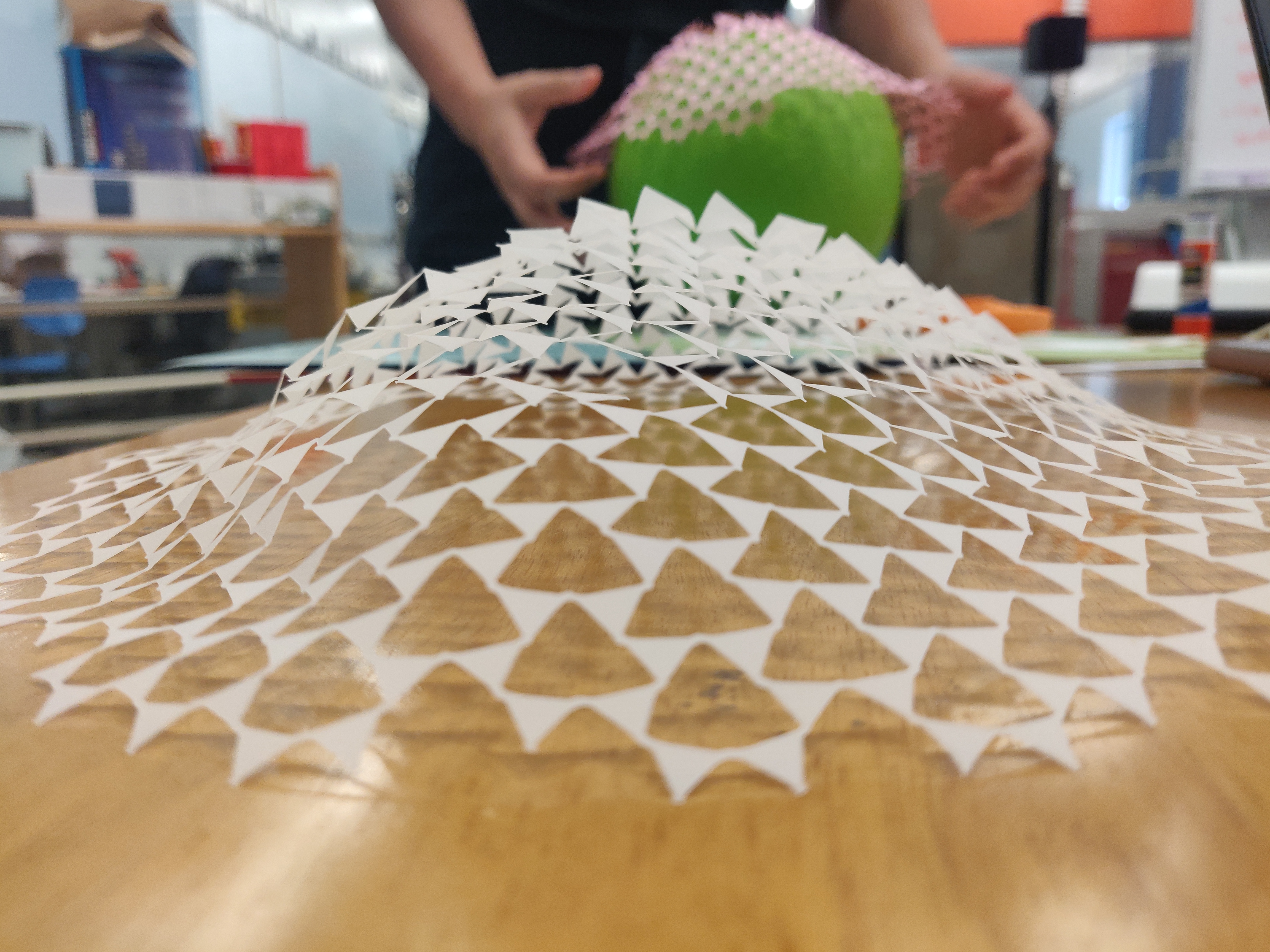
I am not entirely sure as to why the structure is unable to fully deploy, but I have a few hypothesis. The first is that the material itself is very rigid allowing for little deformation. The second: the scaling of the size of the auxetic cells plays a role in how rigid the structure is and influence the out of plane deformations (some of this was somewhat observed with the large unit cell.
Some future directions for this work is looking into mechanical properties that are meaningful in structures and thinking of how those might translate into these auxetic structures.