Fabrication of an Elastic Geodesic Grid
Delsin Carbonell design auxetics structures lasercutter grid fabricationThis week, I worked on the fabrication of an elastic geodesic grid.
I started with these plans in a PDF format.
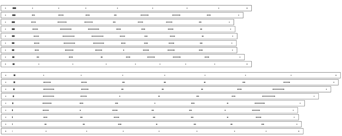
Then I had to convert the PDF file into a readable DXF file to open it in Inkscape. I resized the the plans to fit a 12" x 24" space and adjusted each pin hole/slot to be able to fit a 2mm diameter screw. Once the edits were made and complete, I printed the design to JobControl, the program that connects to the lasercutter. After some last few preparations, I proceeded to cut the plans on a clear 1.5mm (1/16") thick acrylic sheet that was 12" x 24". This would make each beam about 9mm in width.
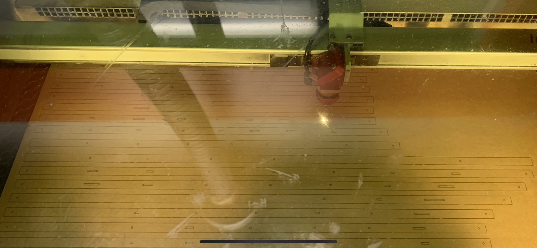
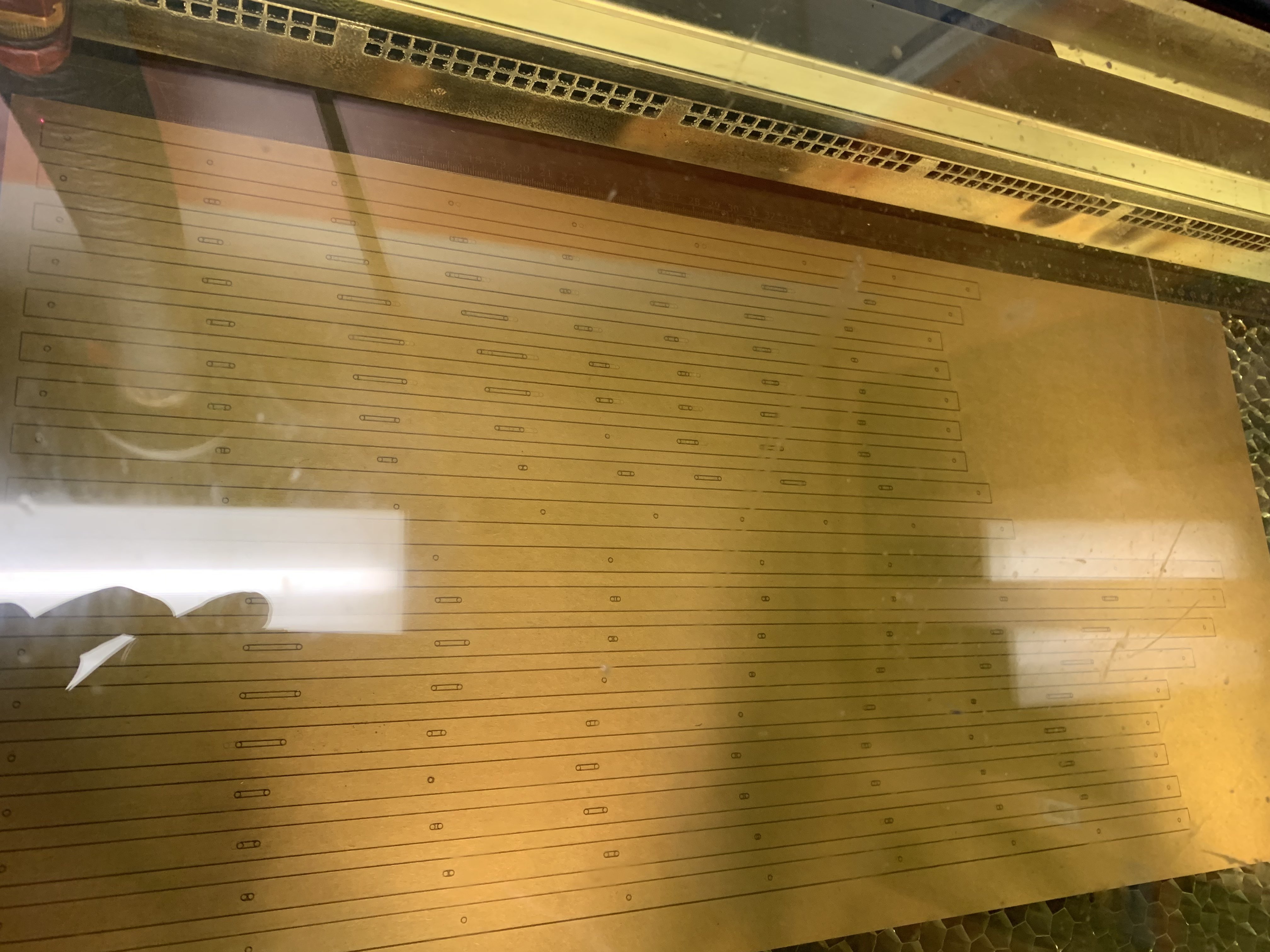
Once the beams were cut out, the holes to fit the 2mm screws I had were just barely not big of enough. To fix this, I took a file and shaved away just enough material to fit the screw and would be able to slide easily within the slot with minimal friction.
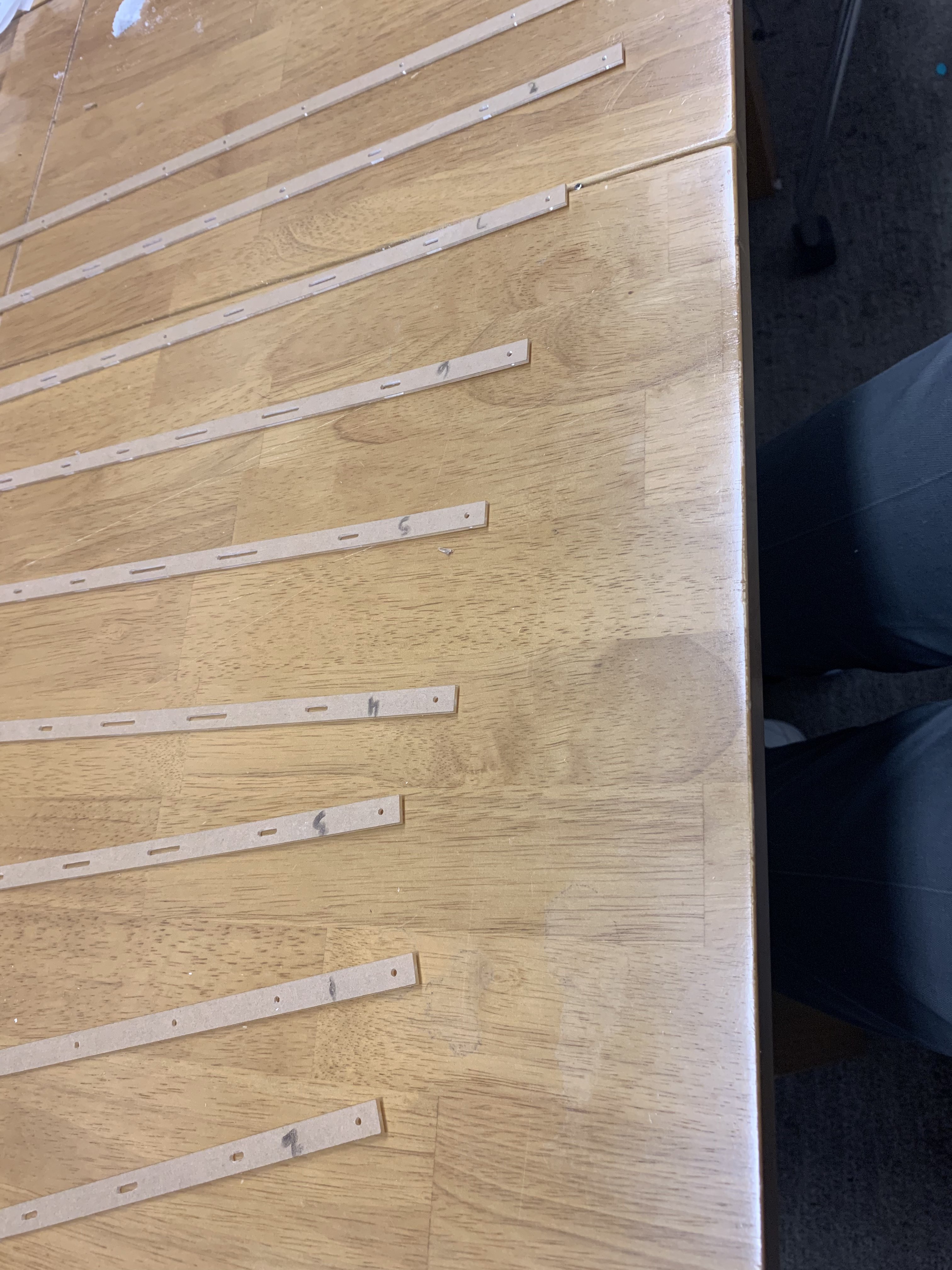
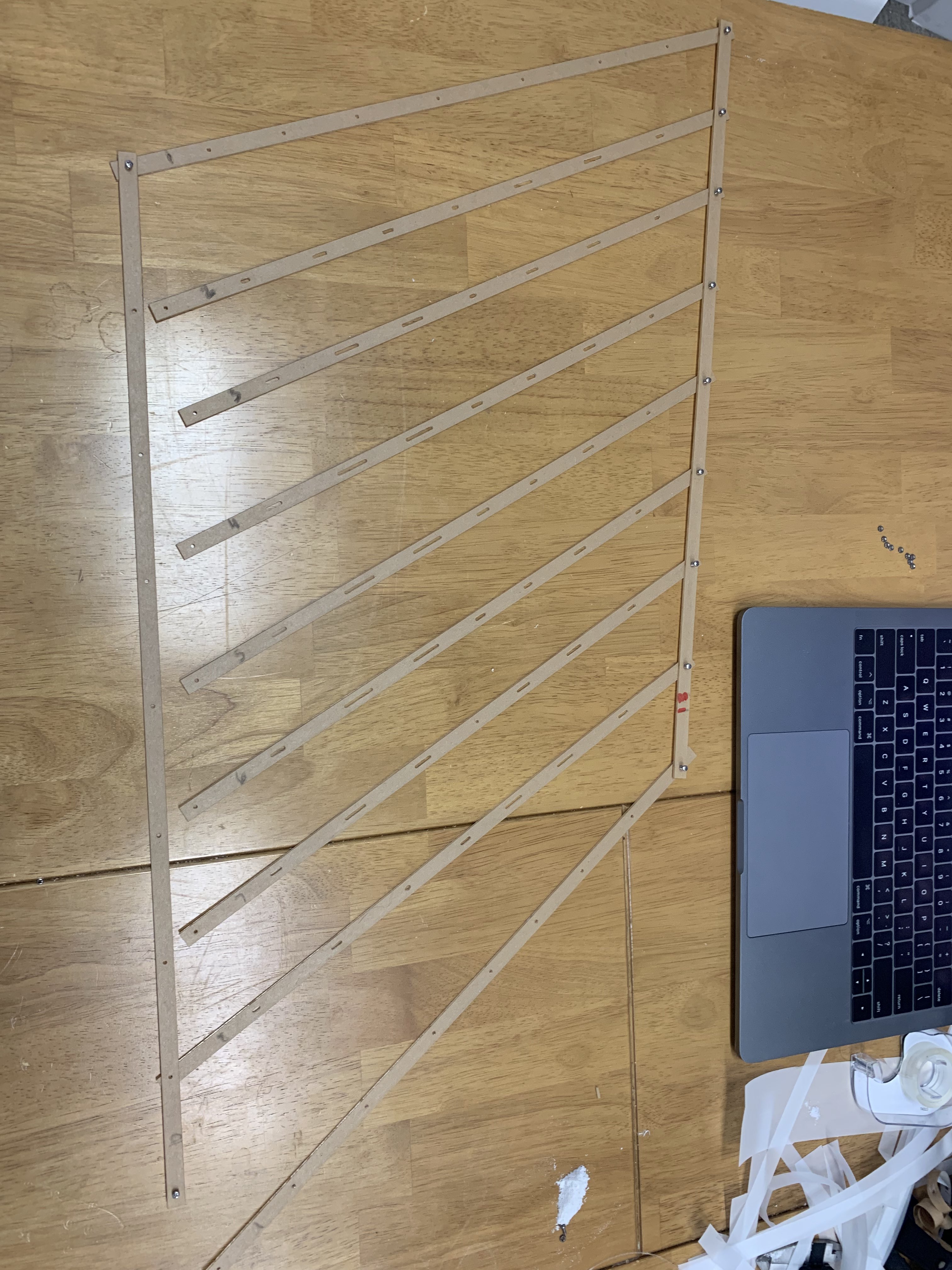
After the painstaking work of filing down each hole, I started to assemble the beams into a grid, slowly securing them together with the screws and hex nuts. It would take 81 screws and nuts to complete the build.
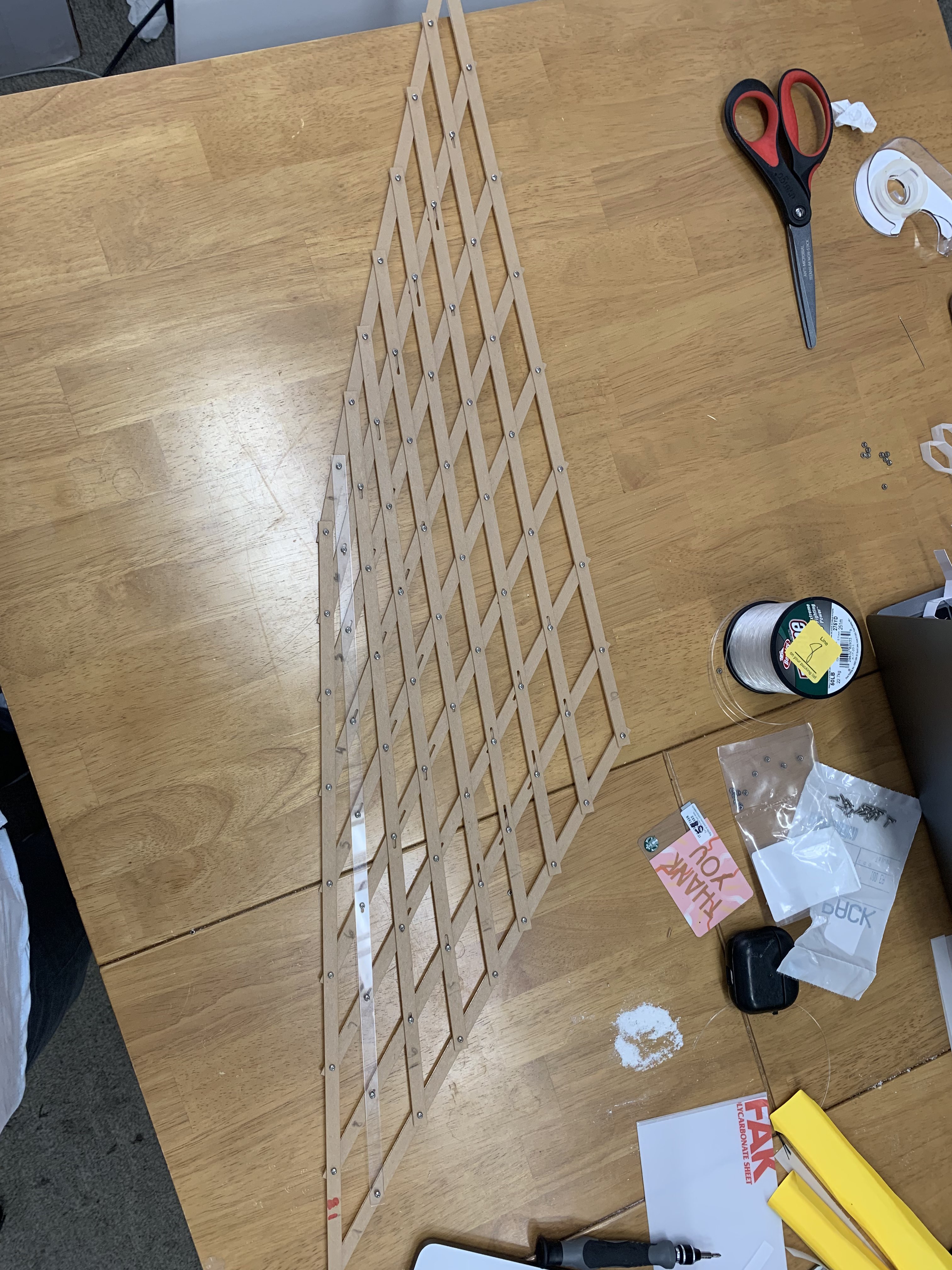
The complete elastic geodesic works as intended and approximates a generic curve and demonstrates 2D planar to 3D spatial deployment.
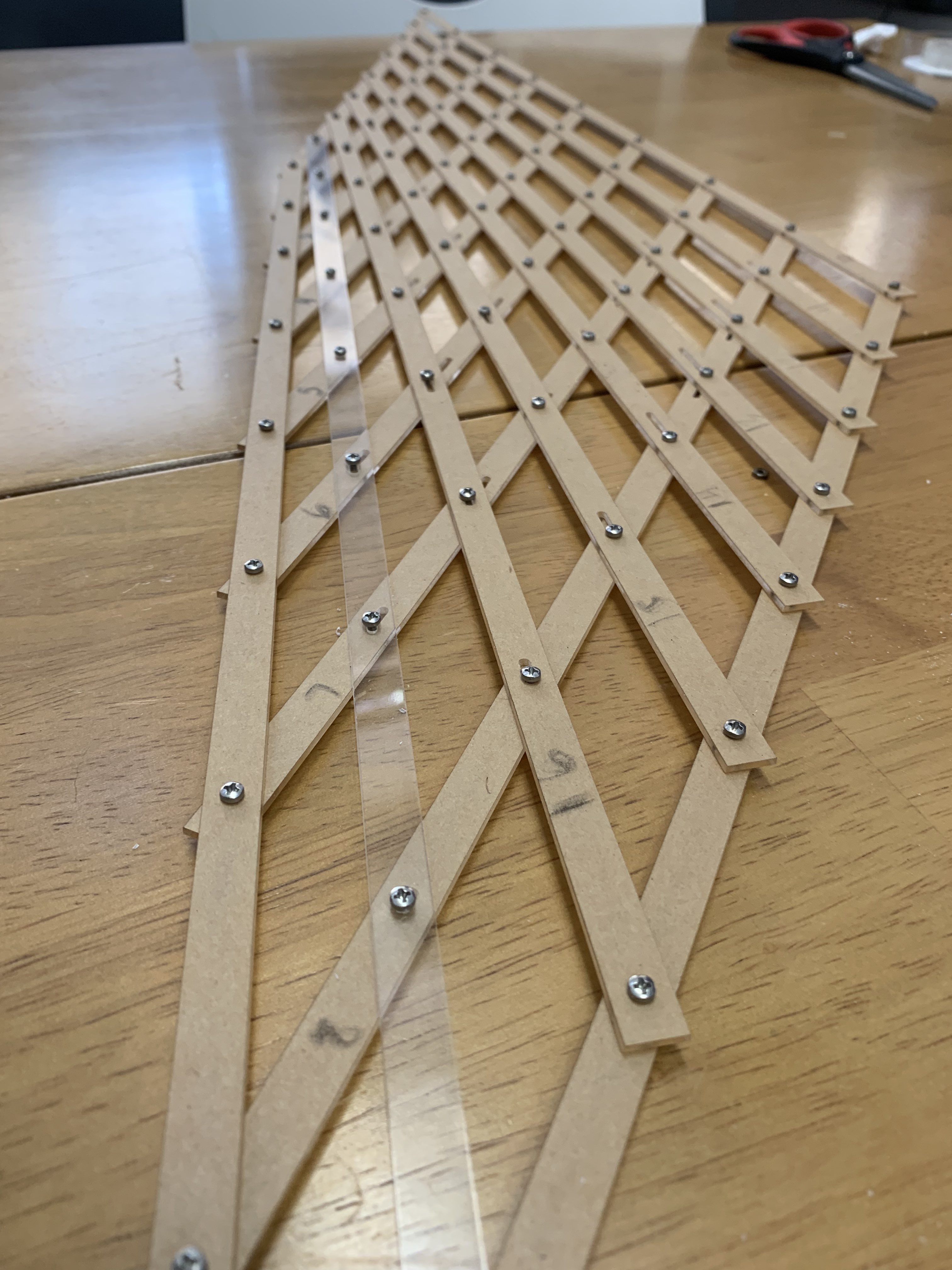
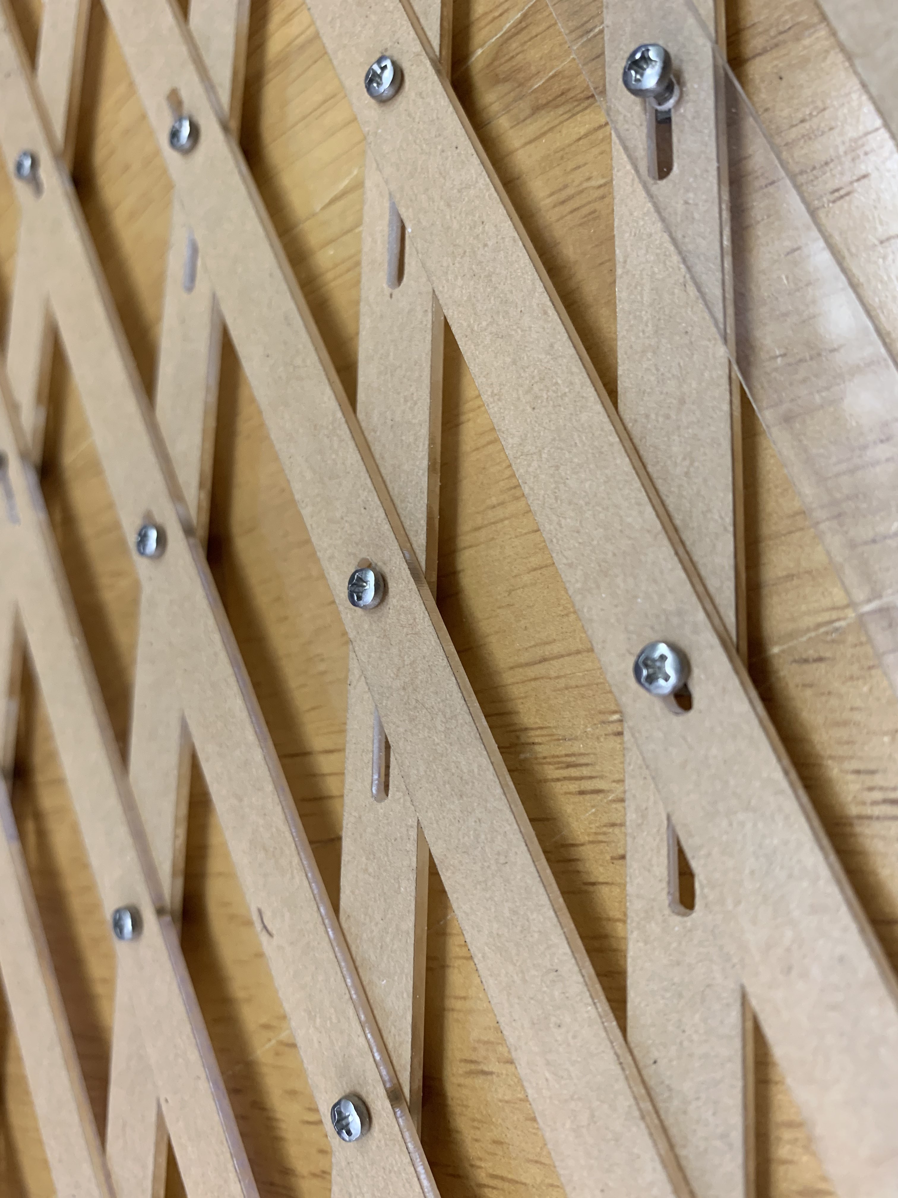
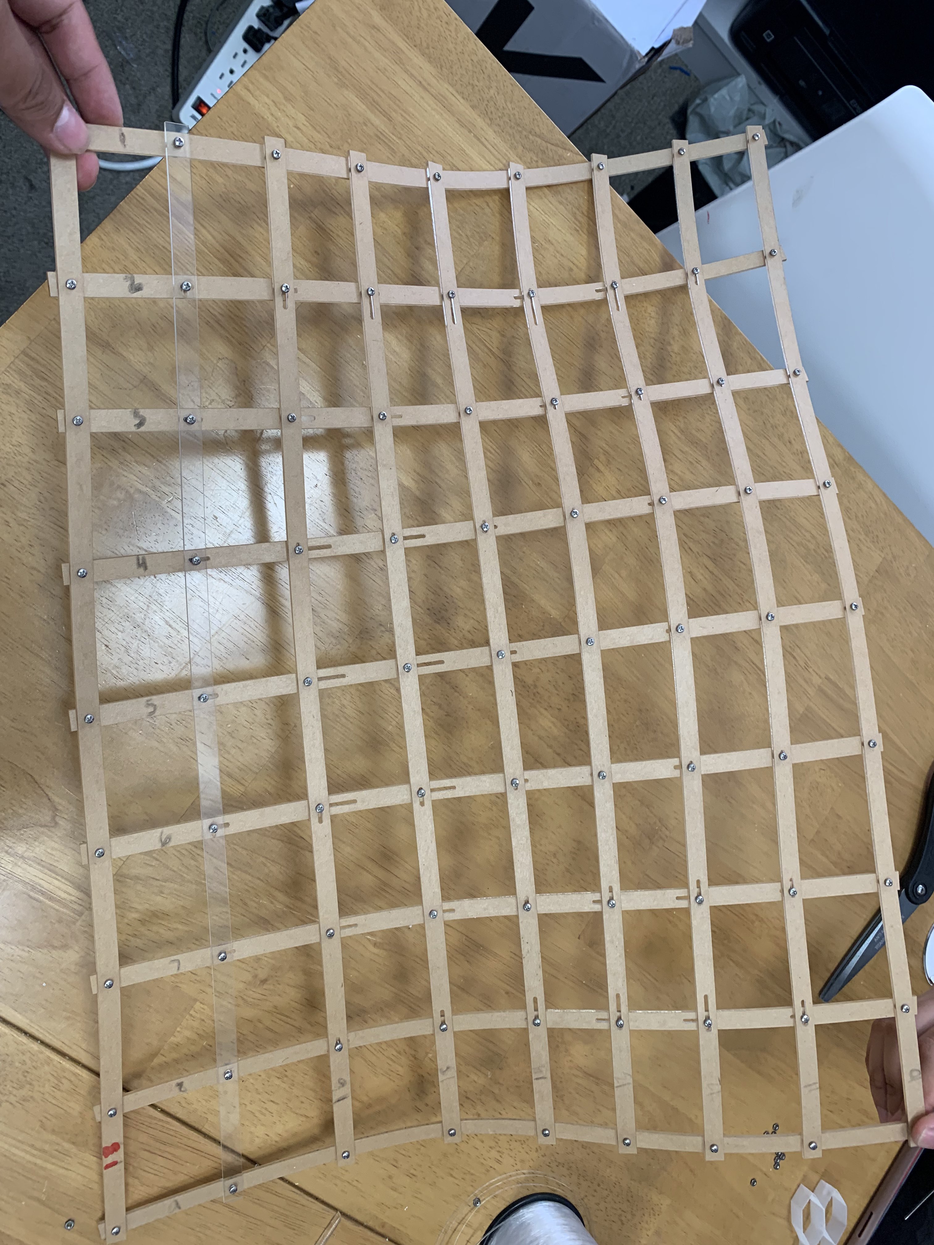
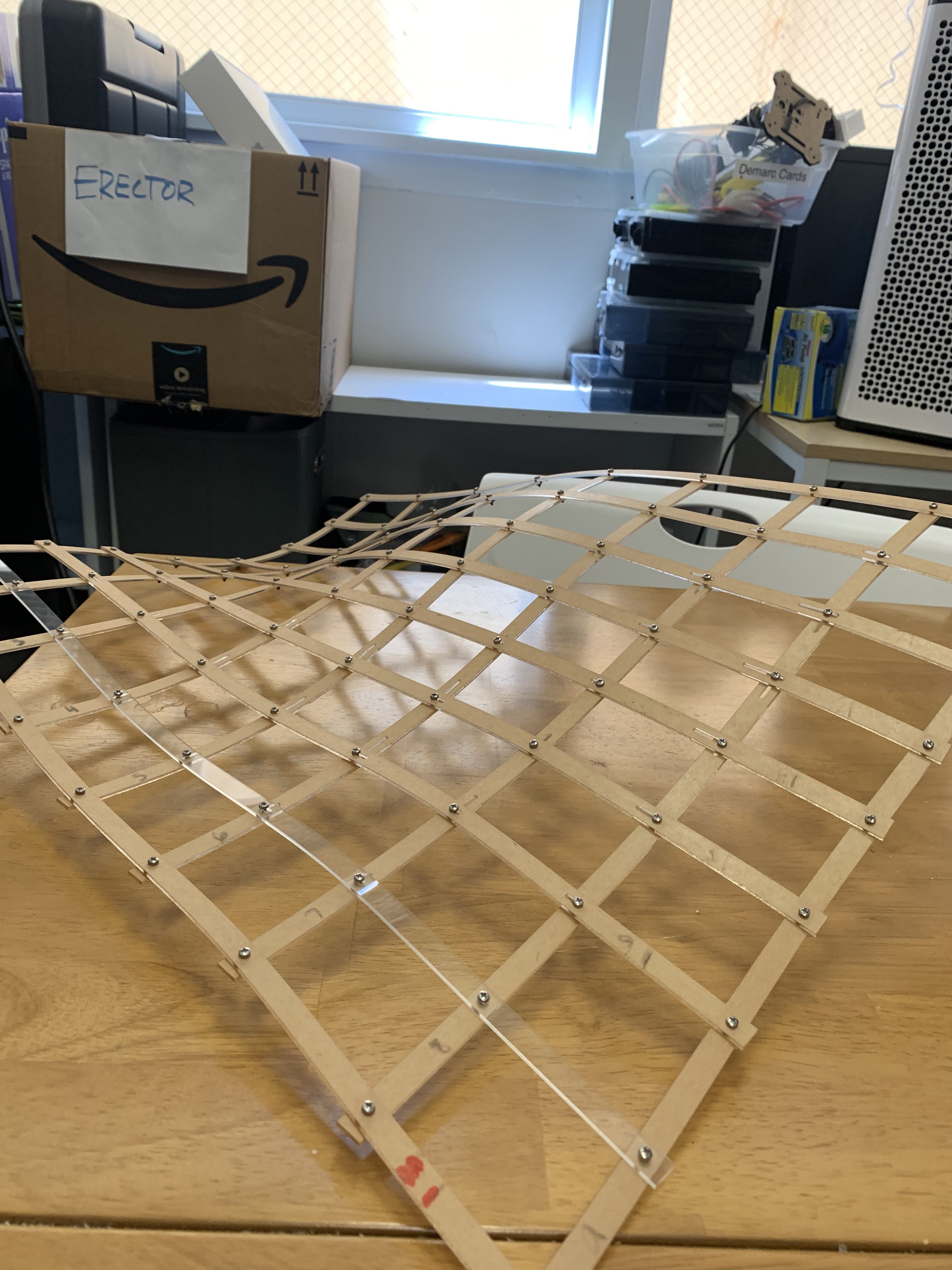
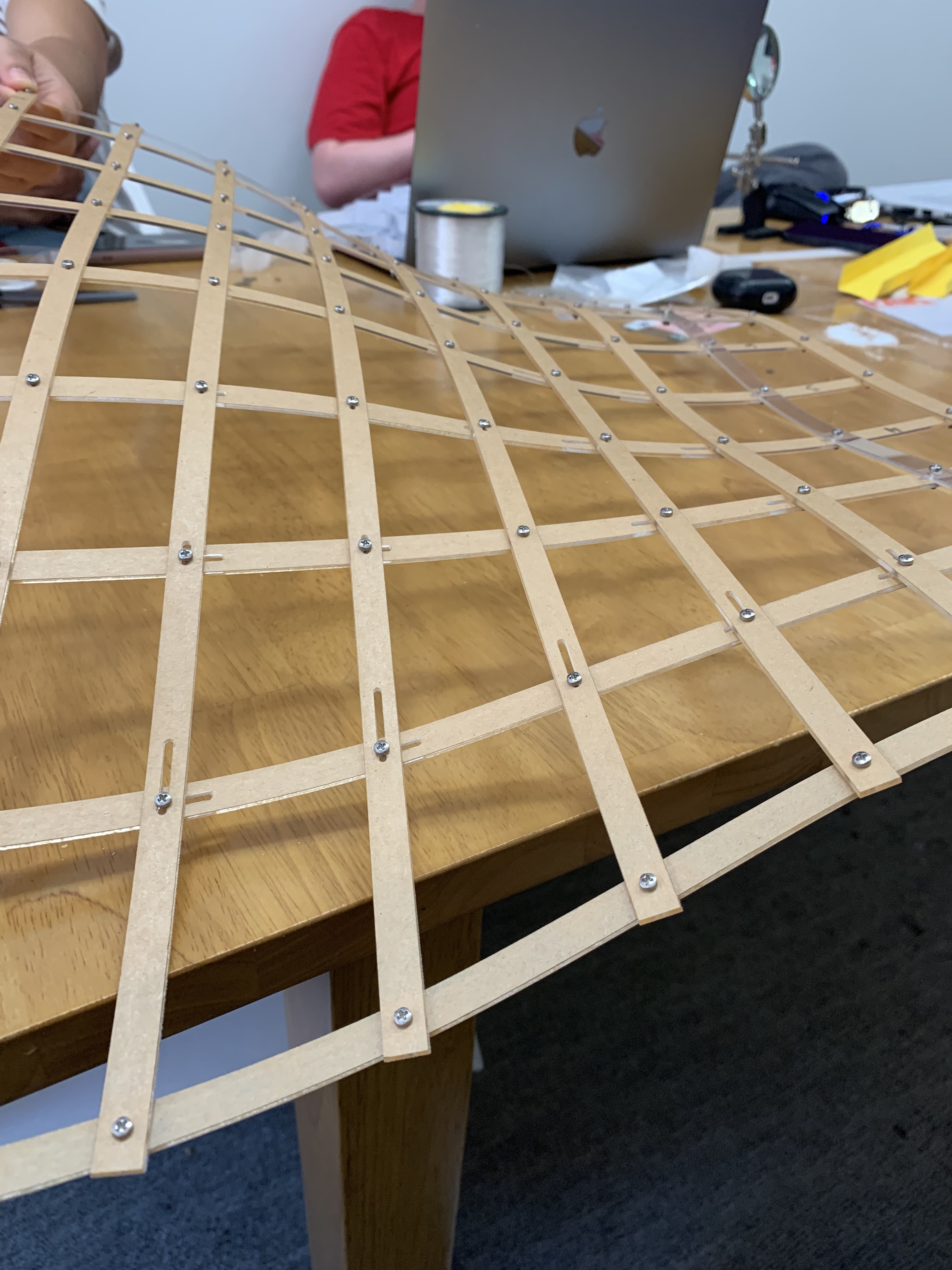
To be able to more efficiently repeat this process, I would need to resize the holes on the lasercutting plans so I wouldn't need to file down each hole one by one again. It would ideally be ready to assemble right off of the lasercutter.