Designing New Modular Robotic Components and Programming Motors to Simulate Motion
William ShihThis past week, I focused on designing more modular components to add to Roco as well as programming motors using the Arduino microcontroller to familiarize and simulate different types of motion. I was able to understand Roco much better through the process of designing these new components; specifically, I am now much more familiar with the tab connections sizing, connection angles, and adding new shapes functionalities much better.
I designed 2 new robot bodies, one which is a simple rectangular and another with a triangular head which I used a right triangle for.
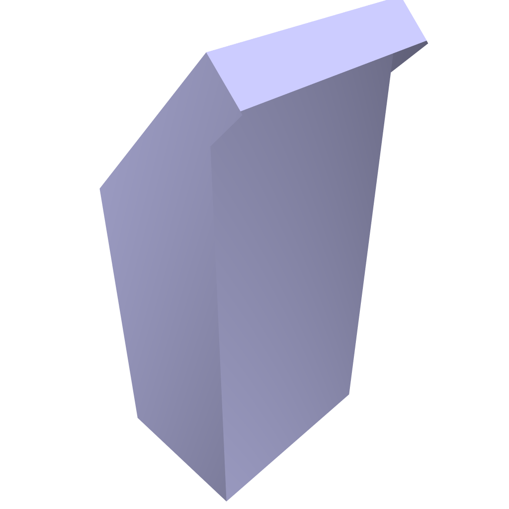
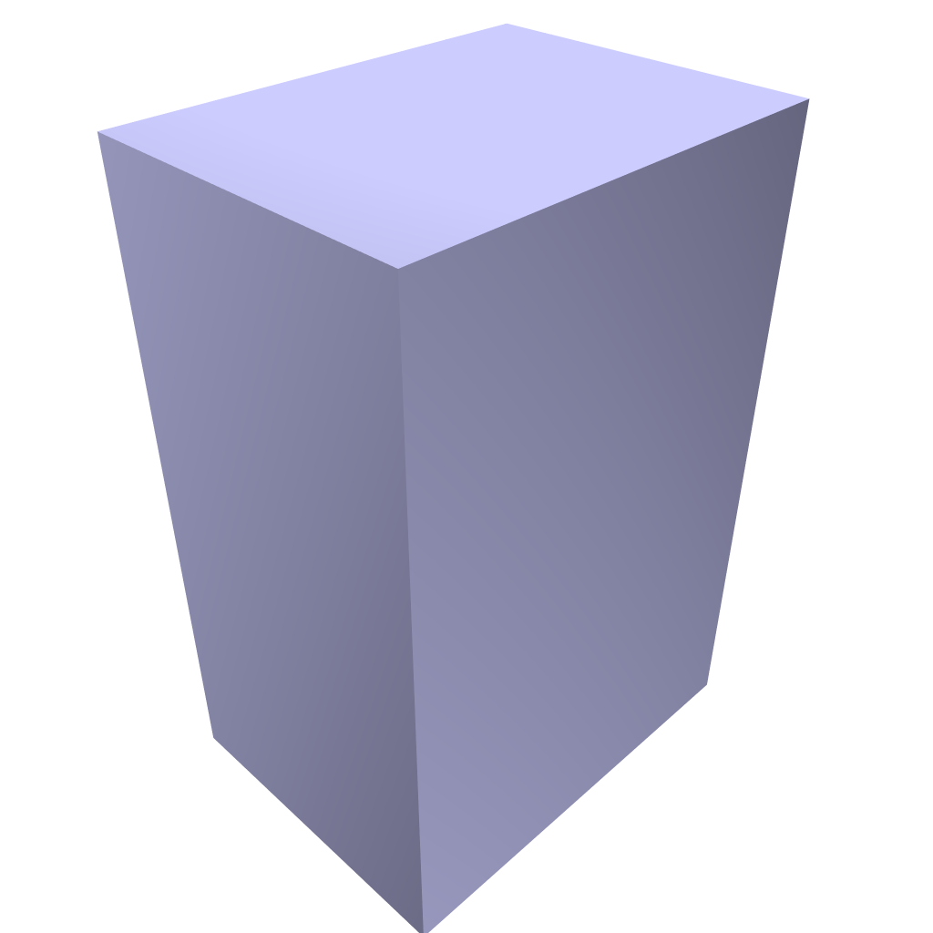
I also designed 2 robot legs
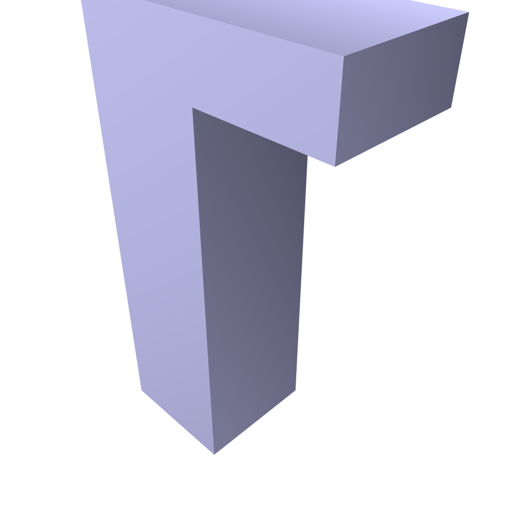
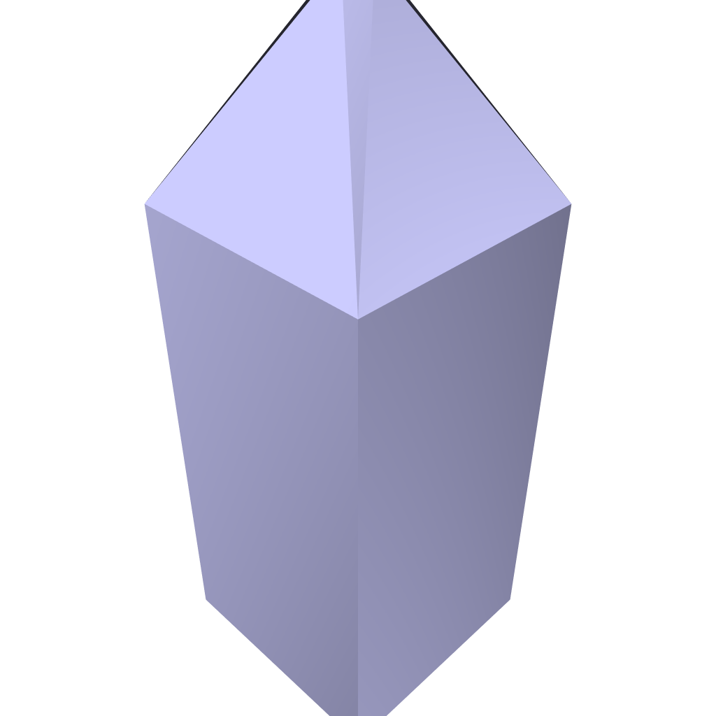
Finally, I made a peripheral as well which is just a simple load carrier, an open rectangular prism
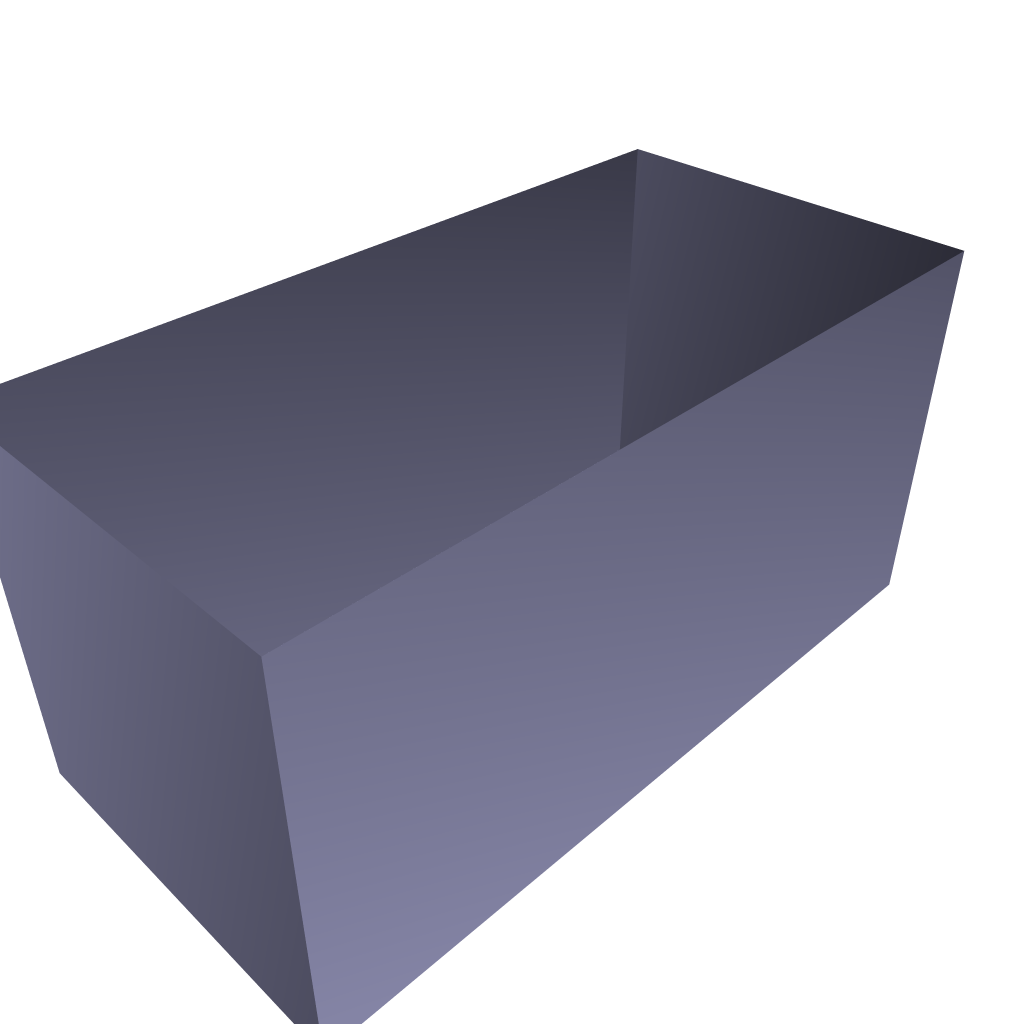
I printed a few and folded them to ensure the computer generated designs were valid and matched with what I visualized.
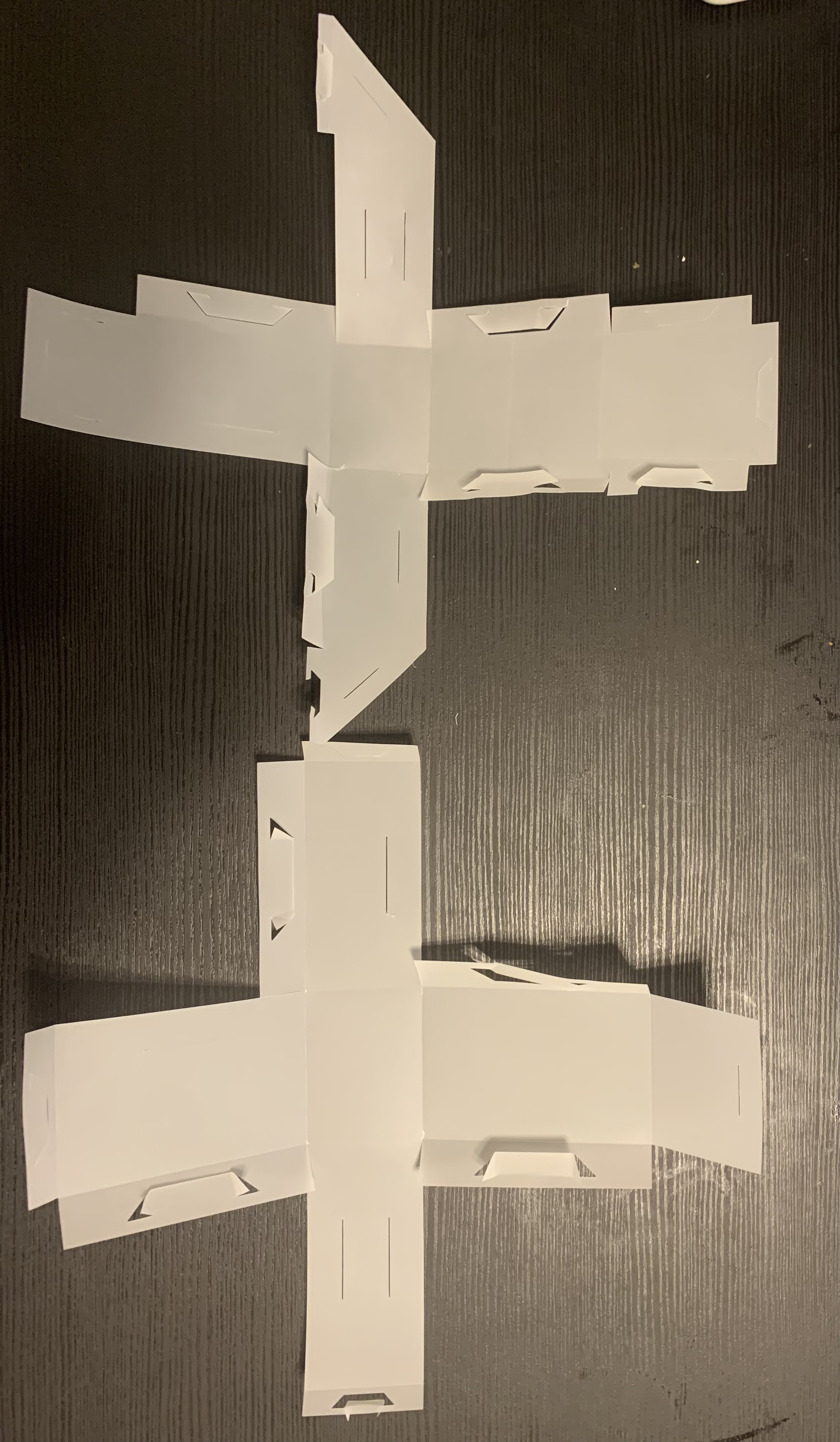
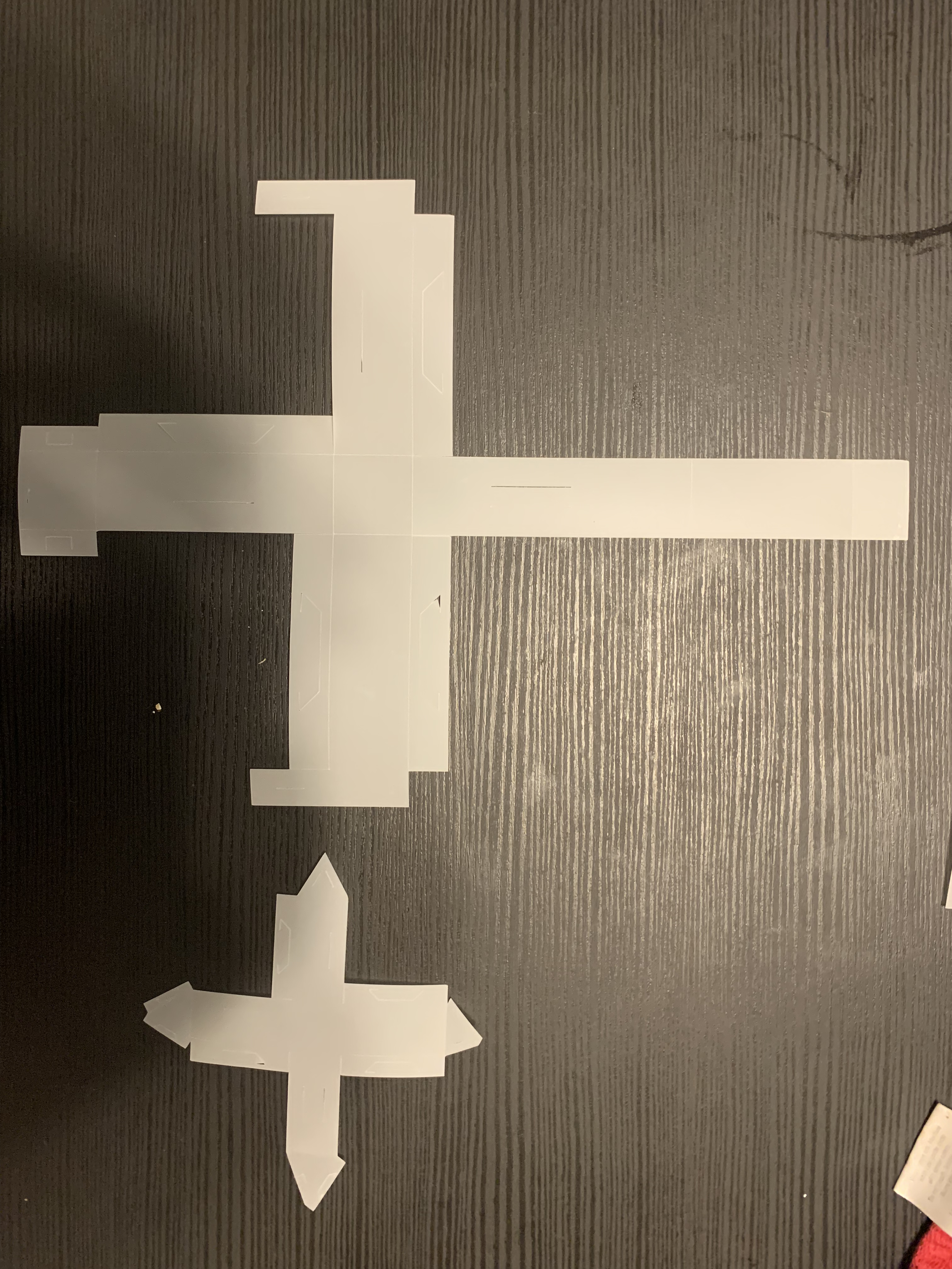
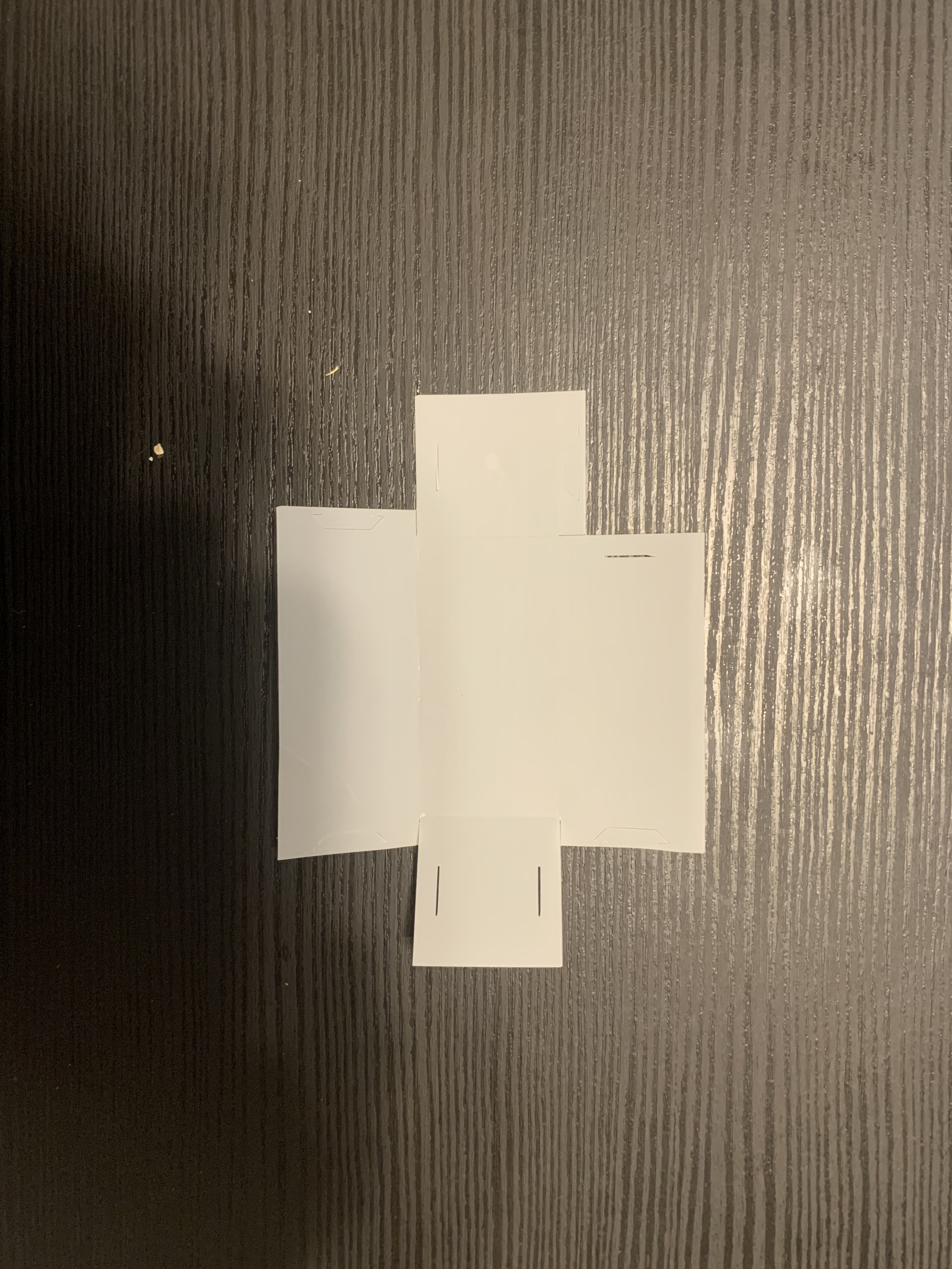
I tried different materials which included cardstack and acrylic paper and used the following laser cutter settings on silhouette studios to coordinate with Cameo: Cardstock Cut: Blade: 10; Passes: 1; Force: 28; Speed: 4 Score: Blade: 7; Passes: 1; Force: 5; Speed: 3 Acrylic Cut: Blade: 10; Passes: 2; Force: 33; Speed: 5 Score: Blade: 10; Passes: 1; Force: 24; Speed: 4
A major limitation I noticed so far was having inconsistent measurements on designs. Specifically, it was difficult to make edge lengths precise in Silhouette Studio as the whole design would expand proportionally. I see this as an issue because this is crucial for the design of the overall robot when putting the components together. Another limitation was that the tabs that are generated by RoCo connections are slightly difficult to fold and insert in their corresponding incisions. It becomes increasingly harder when folding the last few tabs as the structure begins to close. Additionally, this would make it more difficult to produce smaller designs such as robot legs as the tabs would be difficult to fold and could easily tear.
I am currently working on two more body designs, one with isosceles triangles and one with trapezoids and isosceles triangles. I am also working on a 3D wheel design with a decagon.
Aside from making new designs in Roco, I also started trying to simulate different robotic motions with motors in Arduino. I used SG51R motos to simulate coordinated leg motion and FS90R motos to simulate continuous wheel motion. I used 4 SG51R motors and attached axes to simulate
quadruped motion. I attached a cardstock circular cutout onto the FS90R moto with a dot on its edge to observe the rotational motion during testing.
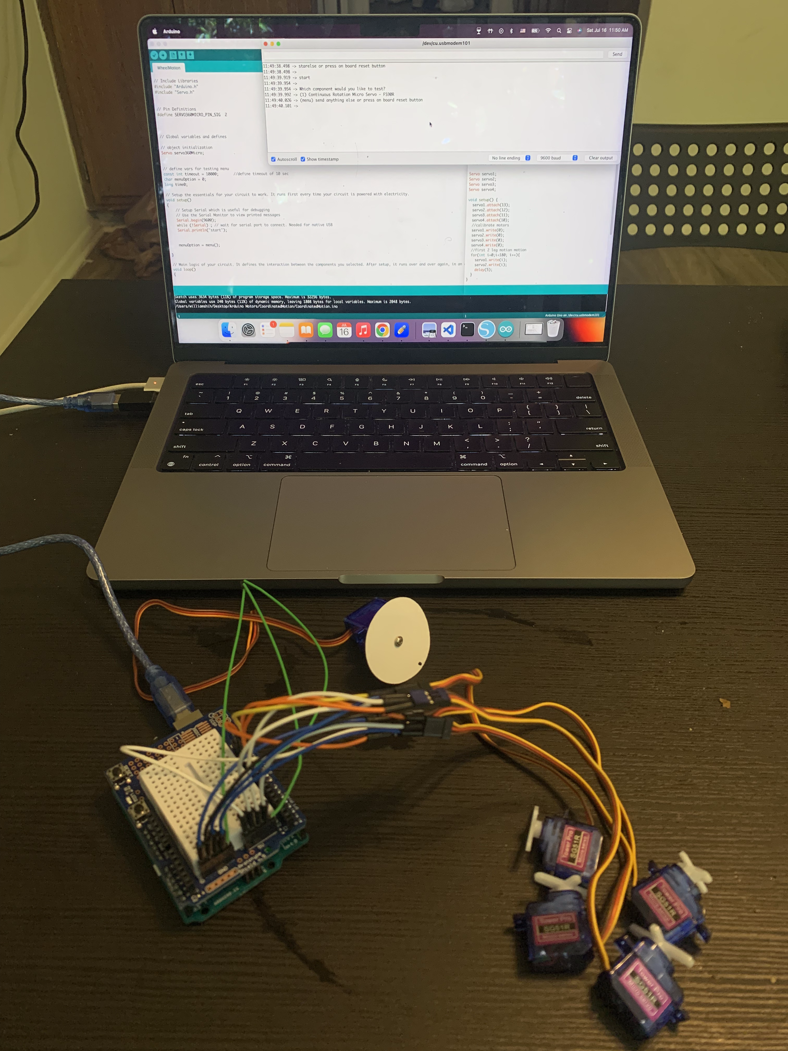
Although these were quite successful, the difficult part will now be assembling all these components together in a coherent design that can accomplish simple tasks such as ground locomotion. I need to consider fitting the electronic parts within the design which concerns the ability of the design and material of the structure to hold up weight as well as cutting holes within the structure to allow the motors to make connections to other components. This coming week I will continue to design more robotic parts in RoCo while trying to assemble my first wheeled robot.